Unlock new dimensions of control with TTP224 and ATmega328P
Begin with a simple touch

Published Feb 14, 2024
Click board™
TouchKey Click
Dev. board
Arduino UNO Rev3
Compiler
NECTO Studio
MCU
ATmega328P
Explore the possibilities of capacitive touch sensing and create interfaces that redefine user interactions
A
A
Hardware Overview
How does it work?
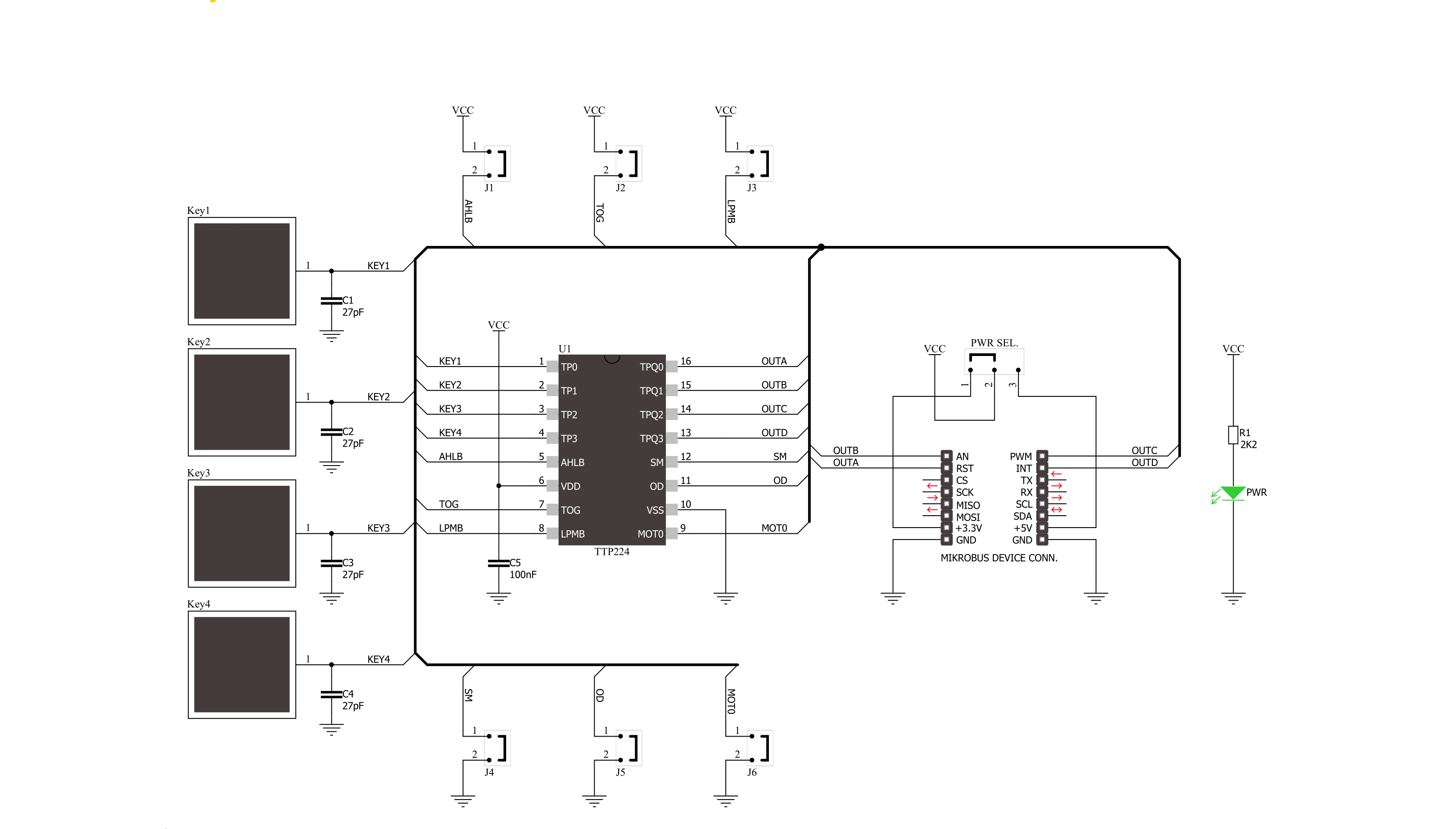
TouchKey Click is based on the TTP224, a four key touch pad detector from TonTouch. The TTP224 has a stable sensing method that can cover diverse conditions and acts as a human interface control panel through non-conductive dielectric materials. It features auto-calibration for life, with a re-calibration period of about 4 seconds when a key has not been touched. The TouchKey Click can detect all four pad activations at once. There are two operating modes: Low Power and Fast mode. Unlike the low-power operating mode, which has a slower response for the first touch, the Fast mode, in addition to a much faster response, also has a slightly higher consumption. When working in Fast mode, if no touch is detected after 8 seconds, the board automatically switches to Low
Power mode. The TouchKey Click has four pads labeled A, B, C, and D. To communicate with the host MCU, the TTP224 uses four digital inputs of the mikroBUS™ socket, labeled just as the pads above, A, B, C, and D. Every touch on the corresponding pad will send the digital state to its assigned pin. The TTP224 has various features that can be addressed on this Click board™ over four solder jumpers. The Low Power or Fast mode option can be set over an LPMB solder jumper (Low Power as a default), while the TOG jumper sets output mode, direct or toggle (direct as a default). Depending on the output state needs, this Click board™ can use active High or Low over the AHLB solder jumper, where the active High is set by default. Objects used to cover the sensor
pads can cause a change in sensing detection. To prevent this change, the maximum key duration time can be set from 16 seconds to infinite via the MOT0 solder jumper (infinite is set as default). Open drain or CMOS output can also be set via the OD solder jumper, with CMOS as the default. The last is an SM solder jumper used to set single or multi-key options, with the multi-key set as the default. This Click board™ can operate with either 3.3V or 5V logic voltage levels selected via the PWR SEL jumper. This way, both 3.3V and 5V capable MCUs can use the communication lines properly. Also, this Click board™ comes equipped with a library containing easy-to-use functions and an example code that can be used as a reference for further development.

Features overview
Development board
Arduino UNO is a versatile microcontroller board built around the ATmega328P chip. It offers extensive connectivity options for various projects, featuring 14 digital input/output pins, six of which are PWM-capable, along with six analog inputs. Its core components include a 16MHz ceramic resonator, a USB connection, a power jack, an
ICSP header, and a reset button, providing everything necessary to power and program the board. The Uno is ready to go, whether connected to a computer via USB or powered by an AC-to-DC adapter or battery. As the first USB Arduino board, it serves as the benchmark for the Arduino platform, with "Uno" symbolizing its status as the
first in a series. This name choice, meaning "one" in Italian, commemorates the launch of Arduino Software (IDE) 1.0. Initially introduced alongside version 1.0 of the Arduino Software (IDE), the Uno has since become the foundational model for subsequent Arduino releases, embodying the platform's evolution.

Microcontroller Overview
MCU Card / MCU

Architecture
AVR
MCU Memory (KB)
32
Silicon Vendor
Microchip
Pin count
28
RAM (Bytes)
2048
You complete me!
Accessories
Click Shield for Arduino UNO has two proprietary mikroBUS™ sockets, allowing all the Click board™ devices to be interfaced with the Arduino UNO board without effort. The Arduino Uno, a microcontroller board based on the ATmega328P, provides an affordable and flexible way for users to try out new concepts and build prototypes with the ATmega328P microcontroller from various combinations of performance, power consumption, and features. The Arduino Uno has 14 digital input/output pins (of which six can be used as PWM outputs), six analog inputs, a 16 MHz ceramic resonator (CSTCE16M0V53-R0), a USB connection, a power jack, an ICSP header, and reset button. Most of the ATmega328P microcontroller pins are brought to the IO pins on the left and right edge of the board, which are then connected to two existing mikroBUS™ sockets. This Click Shield also has several switches that perform functions such as selecting the logic levels of analog signals on mikroBUS™ sockets and selecting logic voltage levels of the mikroBUS™ sockets themselves. Besides, the user is offered the possibility of using any Click board™ with the help of existing bidirectional level-shifting voltage translators, regardless of whether the Click board™ operates at a 3.3V or 5V logic voltage level. Once you connect the Arduino UNO board with our Click Shield for Arduino UNO, you can access hundreds of Click boards™, working with 3.3V or 5V logic voltage levels.

Used MCU Pins
mikroBUS™ mapper
Take a closer look
Click board™ Schematic
Step by step
Project assembly

Start by selecting your development board and Click board™. Begin with the Arduino UNO Rev3 as your development board.


Track your results in real time
Application Output
1. Application Output - In Debug mode, the 'Application Output' window enables real-time data monitoring, offering direct insight into execution results. Ensure proper data display by configuring the environment correctly using the provided tutorial.

2. UART Terminal - Use the UART Terminal to monitor data transmission via a USB to UART converter, allowing direct communication between the Click board™ and your development system. Configure the baud rate and other serial settings according to your project's requirements to ensure proper functionality. For step-by-step setup instructions, refer to the provided tutorial.

3. Plot Output - The Plot feature offers a powerful way to visualize real-time sensor data, enabling trend analysis, debugging, and comparison of multiple data points. To set it up correctly, follow the provided tutorial, which includes a step-by-step example of using the Plot feature to display Click board™ readings. To use the Plot feature in your code, use the function: plot(*insert_graph_name*, variable_name);. This is a general format, and it is up to the user to replace 'insert_graph_name' with the actual graph name and 'variable_name' with the parameter to be displayed.

Software Support
Library Description
This library contains API for TouchKey Click driver.
Key functions:
touchkey_a- This function gets state of "a" (RST) pin on TouchKey Clicktouchkey_b- This function gets state of "b" (AN) pin on TouchKey Clicktouchkey_c- This function gets state of "c" (PWM) pin on TouchKey Clicktouchkey_d- This function gets state of "d" (INT) pin on TouchKey Click
Open Source
Code example
The complete application code and a ready-to-use project are available through the NECTO Studio Package Manager for direct installation in the NECTO Studio. The application code can also be found on the MIKROE GitHub account.
/*!
 * \file
 * \brief TouchKey Click example
 *
 * # Description
 * This application has four capacitive pads powered by TTP224, a touchpad detector IC.
 * Capacitive buttons like these can be toggled even when placed under a layer of glass or paper.
 *
 * The demo application is composed of two sections :
 *
 * ## Application Init
 * Initialization driver enables GPIO and also starts write log.
 *
 * ## Application Task
 * This example demonstrates the use of TouchKey Click board.
 * Detects whether any of the keys is pressed. Results are being sent to the Usart Terminal,
 * where you can track changes.
 *
 * \author MikroE Team
 *
 */
// ------------------------------------------------------------------- INCLUDES

#include "board.h"
#include "log.h"
#include "touchkey.h"

// ------------------------------------------------------------------ VARIABLES

static touchkey_t touchkey;
static log_t logger;

static uint8_t key_state = 0;
static uint8_t key_state_old = 1;

// ------------------------------------------------------ APPLICATION FUNCTIONS

void application_init ( void )
{
    log_cfg_t log_cfg;
    touchkey_cfg_t cfg;

    /**
     * Logger initialization.
     * Default baud rate: 115200
     * Default log level: LOG_LEVEL_DEBUG
     * @note If USB_UART_RX and USB_UART_TX
     * are defined as HAL_PIN_NC, you will
     * need to define them manually for log to work.
     * See @b LOG_MAP_USB_UART macro definition for detailed explanation.
     */
    LOG_MAP_USB_UART( log_cfg );
    log_init( &logger, &log_cfg );
    log_info( &logger, "---- Application Init ----" );

    //  Click initialization.

    touchkey_cfg_setup( &cfg );
    TOUCHKEY_MAP_MIKROBUS( cfg, MIKROBUS_1 );
    touchkey_init( &touchkey, &cfg );
    log_printf( &logger, "Press key\r\n" );
}

void application_task ( void )
{

    key_state = touchkey_a( &touchkey ) | touchkey_b( &touchkey ) | touchkey_c( &touchkey ) | touchkey_d( &touchkey );

    if( key_state == 1 && key_state_old == 0  )
    {
        log_printf( &logger,"Pressed : " );

        if( touchkey_a( &touchkey ) )
        {
            log_printf( &logger, "A\r\n " );
        }
        if( touchkey_b( &touchkey) )
        {
            log_printf( &logger, "B\r\n " );
        }
        if( touchkey_c( &touchkey ) )
        {
            log_printf( &logger, "C\r\n " );;
        }
        if( touchkey_d( &touchkey ) )
        {
            log_printf( &logger, "D\r\n " );
        }
        key_state_old = 1;
    }
    if ( key_state == 0 && key_state_old == 1 )
    {
        key_state_old = 0;
    }

}

int main ( void )
{
    /* Do not remove this line or clock might not be set correctly. */
    #ifdef PREINIT_SUPPORTED
    preinit();
    #endif

    application_init( );

    for ( ; ; )
    {
        application_task( );
    }

    return 0;
}

// ------------------------------------------------------------------------ END
Additional Support
Resources
Category:Capacitive


