Provide valuable information about the power consumption of your system with INA219 and ATmega2560
12-bit power monitor for measuring power consumption
Published Sep 18, 2024
Click board™
Power Monitor 2 Click
Dev. board
Arduino Mega 2560 Rev3
Compiler
NECTO Studio
MCU
ATmega2560
Provide valuable information for monitoring and managing power in embedded systems
A
A
Hardware Overview
How does it work?
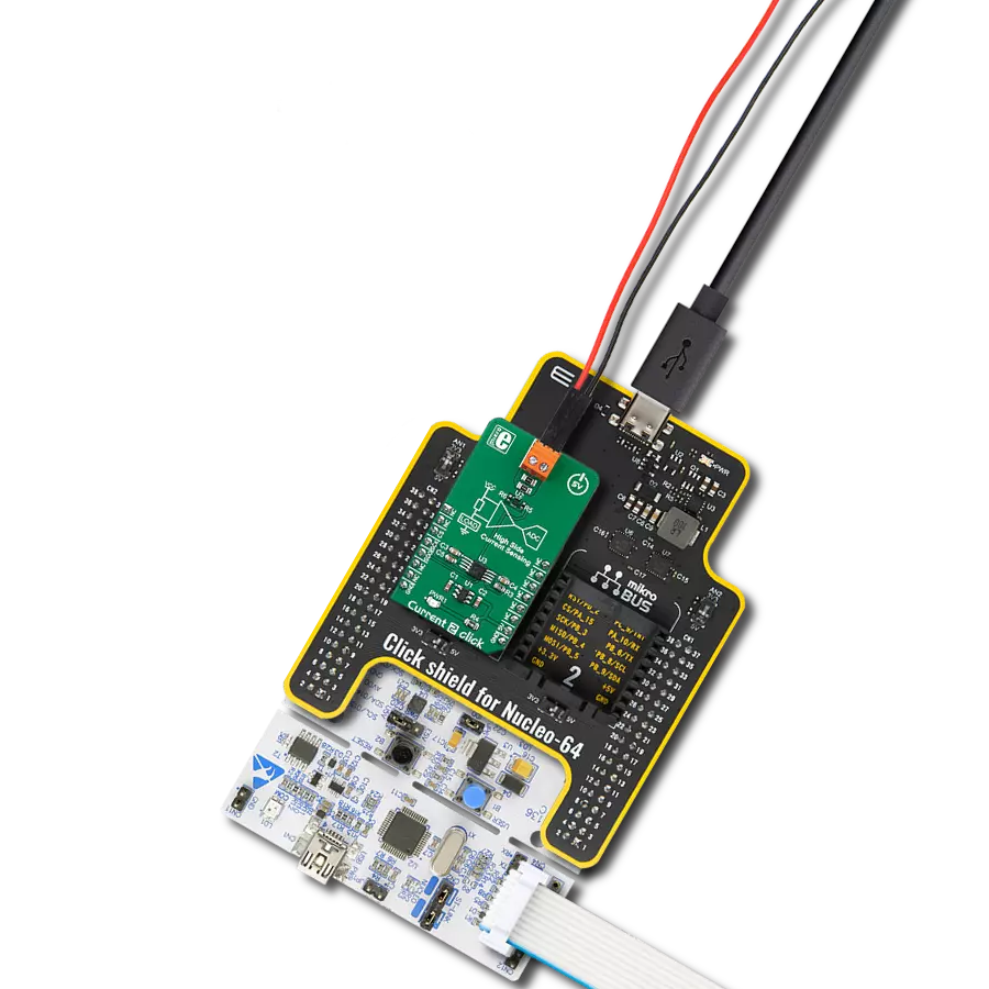
Power Monitoring 2 Click is based on two INA219s, a 12-bit I2C-output digital power monitor from Texas Instruments for precise power monitoring. These ICs are specifically designed to monitor the power consumption of connected load devices by measuring the current and voltage on two separate power rails - 3.3V and 5V - of an additional mikroBUS™ socket. This configuration allows for monitoring these two power lines, ideal for evaluating the power usage of any Click board™ inserted into the onboard mikroBUS™ socket. Thanks to its flexibility, the INA219 allows power monitoring without any special power-supply sequencing, making it capable of monitoring power even when the supply or bus voltage is independently present or absent. The INA219s provide real-time digital readings of current, voltage, and power. It achieves this by sensing the voltage drop across shunt resistors (R3 and R4) connected to the bus of interest, and it can handle
bus voltages ranging from 0 to 26V. The device's programmable conversion times and filtering options ensure accurate measurements under various operating conditions. Additionally, the INA219 offers a programmable calibration value that, when combined with an internal multiplier, enables direct readouts of current in amperes and calculates power in watts through a multiplying register. As mentioned, the INA219 communicates with the host MCU using a standard 2-wire I2C interface, supporting High-Speed mode with clock frequencies up to 1MHz. Each INA219 IC on the Power Monitoring 2 Click has a configurable I2C address, which can be set using the ADDR SEL jumpers. These jumpers (U2 or U3, corresponding to each INA219) allow the selection of the desired I2C address by positioning them to either 0 or 1. Additionally, considering that this Click board™ can operate with both 3.3V and 5V logic levels, the voltage to which the pull-up resistors for the I2C
lines are connected can also be selected. This is achieved using the I2C PULL-UP jumpers, where the appropriate voltage level (3.3V or 5V) is selected by adjusting the jumpers accordingly. This board also features an onboard switch labeled CS SEL, which enables the CS line from the mikroBUS™ socket to communicate with the ClickID feature on the board. The CS line is redirected by setting the switch to the ON position, allowing the ClickID feature to function properly for identifying the connected Click board™. This Click board™ can operate with either 3.3V or 5V logic voltage levels. This way, both 3.3V and 5V capable MCUs can use the communication lines properly. As an added feature, it includes two green LED indicators that show which power rail is active, either 3.3V or 5V. Also, this Click board™ comes equipped with a library containing easy-to-use functions and an example code that can be used as a reference for further development.

Features overview
Development board
Arduino Mega 2560 is a robust microcontroller platform built around the ATmega 2560 chip. It has extensive capabilities and boasts 54 digital input/output pins, including 15 PWM outputs, 16 analog inputs, and 4 UARTs. With a 16MHz crystal
oscillator ensuring precise timing, it offers seamless connectivity via USB, a convenient power jack, an ICSP header, and a reset button. This all-inclusive board simplifies microcontroller projects; connect it to your computer via USB or power it up
using an AC-to-DC adapter or battery. Notably, the Mega 2560 maintains compatibility with a wide range of shields crafted for the Uno, Duemilanove, or Diecimila boards, ensuring versatility and ease of integration.

Microcontroller Overview
MCU Card / MCU

Architecture
AVR
MCU Memory (KB)
256
Silicon Vendor
Microchip
Pin count
100
RAM (Bytes)
8192
You complete me!
Accessories
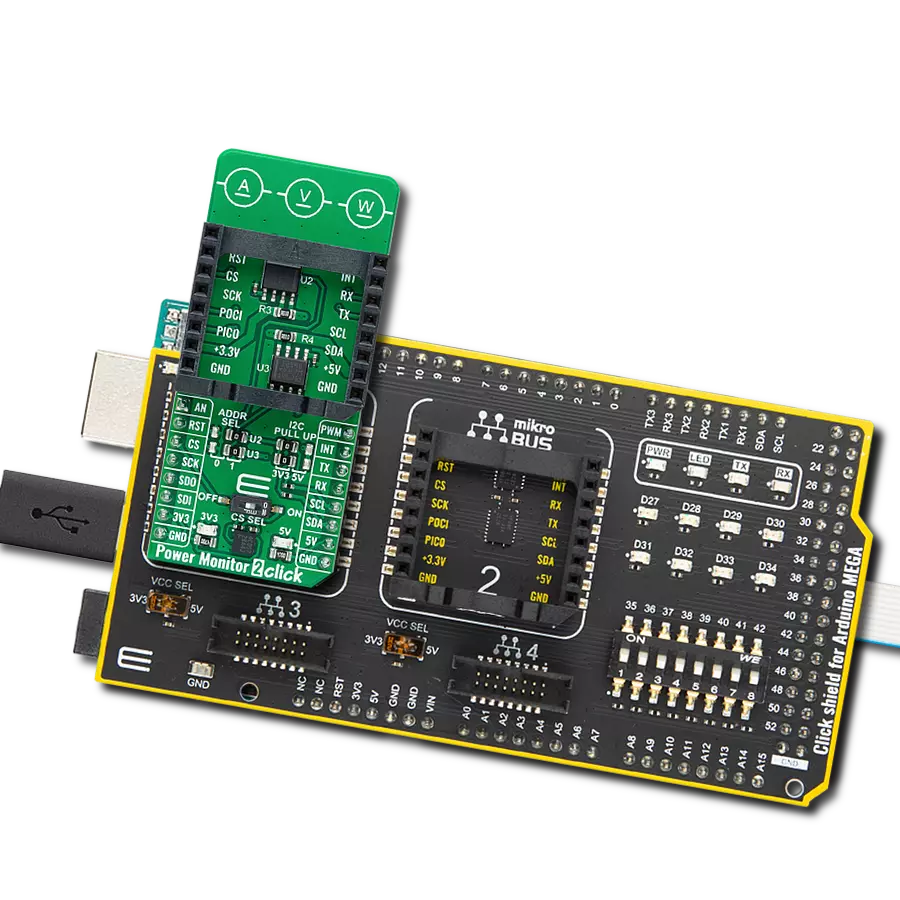
Click Shield for Arduino Mega comes equipped with four mikroBUS™ sockets, with two in the form of a Shuttle connector, allowing all the Click board™ devices to be interfaced with the Arduino Mega board with no effort. Featuring an AVR 8-bit microcontroller with advanced RISC architecture, 54 digital I/O pins, and Arduino™ compatibility, the Arduino Mega board offers limitless possibilities for prototyping and creating diverse applications. This board is controlled and powered conveniently through a USB connection to program and debug the Arduino Mega board efficiently out of the box, with an additional USB cable connected to the USB B port on the board. Simplify your project development with the integrated ATmega16U2 programmer and unleash creativity using the extensive I/O options and expansion capabilities. There are eight switches, which you can use as inputs, and eight LEDs, which can be used as outputs of the MEGA2560. In addition, the shield features the MCP1501, a high-precision buffered voltage reference from Microchip. This reference is selected by default over the EXT REF jumper at the bottom of the board. You can choose an external one, as you would usually do with an Arduino Mega board. There is also a GND hook for testing purposes. Four additional LEDs are PWR, LED (standard pin D13), RX, and TX LEDs connected to UART1 (mikroBUS™ 1 socket). This Click Shield also has several switches that perform functions such as selecting the logic levels of analog signals on mikroBUS™ sockets and selecting logic voltage levels of the mikroBUS™ sockets themselves. Besides, the user is offered the possibility of using any Click board™ with the help of existing bidirectional level-shifting voltage translators, regardless of whether the Click board™ operates at a 3.3V or 5V logic voltage level. Once you connect the Arduino Mega board with Click Shield for Arduino Mega, you can access hundreds of Click boards™, working with 3.3V or 5V logic voltage levels.

Used MCU Pins
mikroBUS™ mapper
Take a closer look
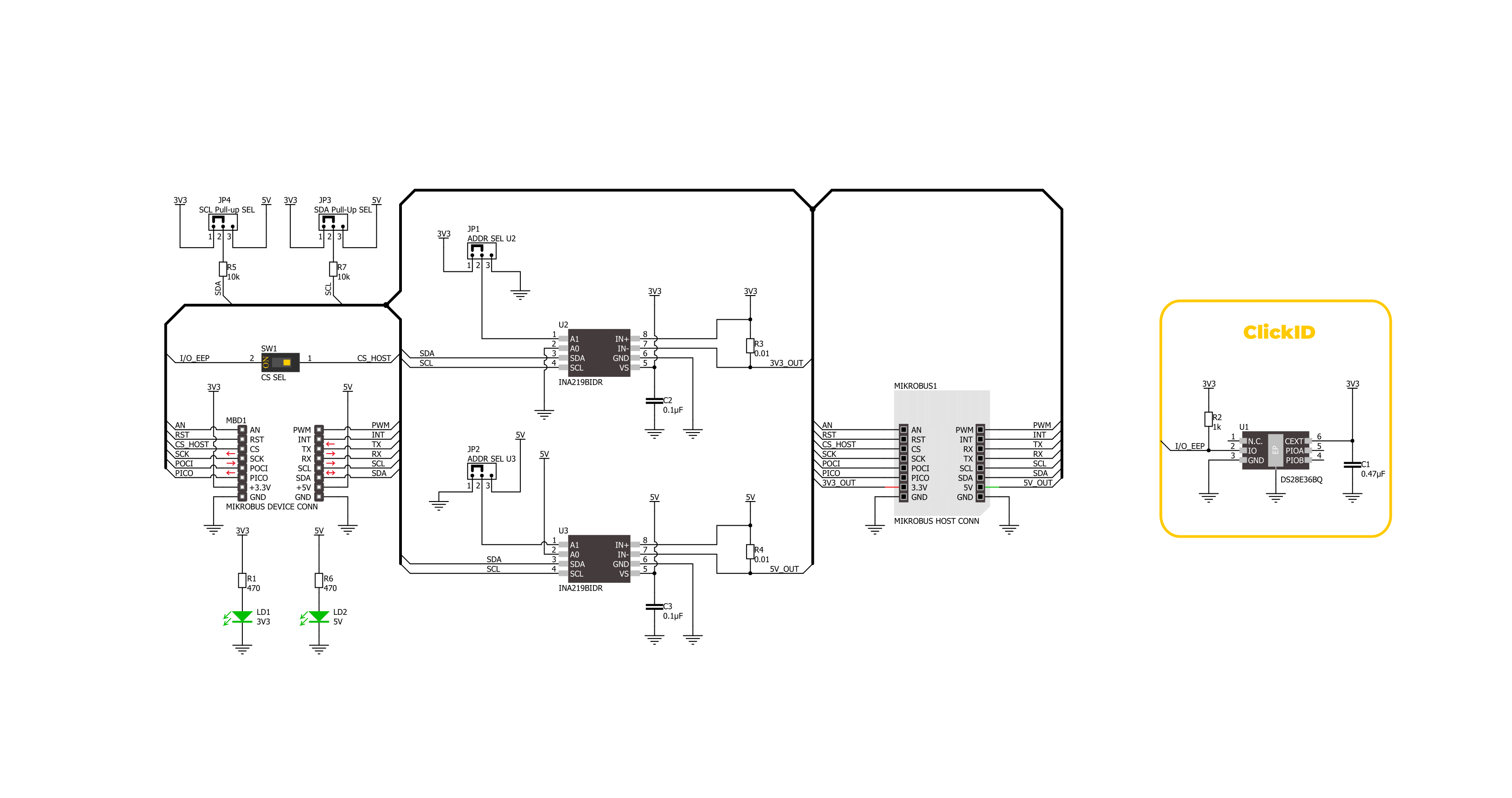
Click board™ Schematic
Step by step
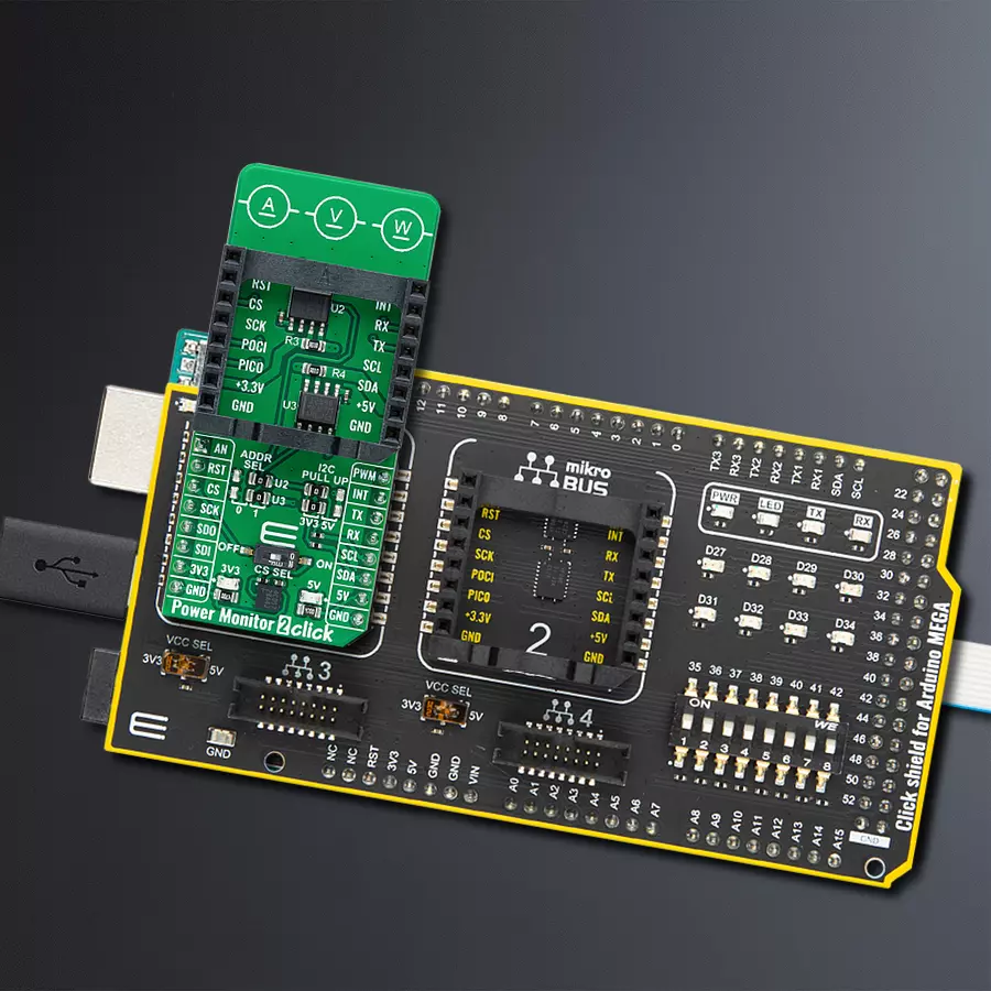
Project assembly

Start by selecting your development board and Click board™. Begin with the Arduino Mega 2560 Rev3 as your development board.


Track your results in real time
Application Output
1. Application Output - In Debug mode, the 'Application Output' window enables real-time data monitoring, offering direct insight into execution results. Ensure proper data display by configuring the environment correctly using the provided tutorial.

2. UART Terminal - Use the UART Terminal to monitor data transmission via a USB to UART converter, allowing direct communication between the Click board™ and your development system. Configure the baud rate and other serial settings according to your project's requirements to ensure proper functionality. For step-by-step setup instructions, refer to the provided tutorial.

3. Plot Output - The Plot feature offers a powerful way to visualize real-time sensor data, enabling trend analysis, debugging, and comparison of multiple data points. To set it up correctly, follow the provided tutorial, which includes a step-by-step example of using the Plot feature to display Click board™ readings. To use the Plot feature in your code, use the function: plot(*insert_graph_name*, variable_name);. This is a general format, and it is up to the user to replace 'insert_graph_name' with the actual graph name and 'variable_name' with the parameter to be displayed.

Software Support
Library Description
This library contains API for Power Monitor 2 Click driver.
Key functions:
powermonitor2_set_address- This function sets the device slave address.powermonitor2_read_data- This function reads the shunt voltage, bus voltage, current, and power data measurements.powermonitor2_read_data_avg- This function reads the shunt voltage, bus voltage, current, and power data measurements averaged from num_conv samples.
Open Source
Code example
The complete application code and a ready-to-use project are available through the NECTO Studio Package Manager for direct installation in the NECTO Studio. The application code can also be found on the MIKROE GitHub account.
/*!
 * @file main.c
 * @brief Power Monitor 2 Click example
 *
 * # Description
 * This example demonstrates the use of Power Monitor 2 Click by reading and displaying
 * the power consumption at 3V3 and 5V of the connected Click board.
 *
 * The demo application is composed of two sections :
 *
 * ## Application Init
 * Initializes the driver and performs the Click default configuration.
 *
 * ## Application Task
 * Reads the voltage, current, and power measurements from U2 and U3 sensors averaged
 * from 20 samples and displays the results on the USB UART.
 *
 * @author Stefan Filipovic
 *
 */

#include "board.h"
#include "log.h"
#include "powermonitor2.h"

static powermonitor2_t powermonitor2;
static log_t logger;

void application_init ( void )
{
    log_cfg_t log_cfg;  /**< Logger config object. */
    powermonitor2_cfg_t powermonitor2_cfg;  /**< Click config object. */

    /**
     * Logger initialization.
     * Default baud rate: 115200
     * Default log level: LOG_LEVEL_DEBUG
     * @note If USB_UART_RX and USB_UART_TX
     * are defined as HAL_PIN_NC, you will
     * need to define them manually for log to work.
     * See @b LOG_MAP_USB_UART macro definition for detailed explanation.
     */
    LOG_MAP_USB_UART( log_cfg );
    log_init( &logger, &log_cfg );
    log_info( &logger, " Application Init " );

    // Click initialization.
    powermonitor2_cfg_setup( &powermonitor2_cfg );
    POWERMONITOR2_MAP_MIKROBUS( powermonitor2_cfg, MIKROBUS_1 );
    if ( I2C_MASTER_ERROR == powermonitor2_init( &powermonitor2, &powermonitor2_cfg ) )
    {
        log_error( &logger, " Communication init." );
        for ( ; ; );
    }

    if ( POWERMONITOR2_ERROR == powermonitor2_default_cfg ( &powermonitor2 ) )
    {
        log_error( &logger, " Default configuration." );
        for ( ; ; );
    }

    log_info( &logger, " Application Task " );
}

void application_task ( void )
{
    powermonitor2_data_t pm_3v3, pm_5v;

    powermonitor2_set_address ( &powermonitor2, powermonitor2.address_3v3 );
    if ( POWERMONITOR2_OK == powermonitor2_read_data_avg ( &powermonitor2, POWERMONITOR2_DEFAULT_NUM_CONV, &pm_3v3 ) )
    {
        log_printf( &logger, " --- 3V3 Power Monitor ---\r\n" );
        log_printf( &logger, " Voltage: %.3f V\r\n", pm_3v3.bus_v );
        log_printf( &logger, " Current: %.3f A\r\n", pm_3v3.current );
        log_printf( &logger, " Power: %.2f W\r\n", pm_3v3.power );
        log_printf( &logger, " -------------------------\r\n" );
    }

    powermonitor2_set_address ( &powermonitor2, powermonitor2.address_5v );
    if ( POWERMONITOR2_OK == powermonitor2_read_data_avg ( &powermonitor2, POWERMONITOR2_DEFAULT_NUM_CONV, &pm_5v ) )
    {
        log_printf( &logger, " ---- 5V Power Monitor ---\r\n" );
        log_printf( &logger, " Voltage: %.3f V\r\n", pm_5v.bus_v );
        log_printf( &logger, " Current: %.3f A\r\n", pm_5v.current );
        log_printf( &logger, " Power: %.2f W\r\n", pm_5v.power );
        log_printf( &logger, " -------------------------\r\n" );
    }

    Delay_ms ( 1000 );
}

int main ( void )
{
    /* Do not remove this line or clock might not be set correctly. */
    #ifdef PREINIT_SUPPORTED
    preinit();
    #endif

    application_init( );

    for ( ; ; )
    {
        application_task( );
    }

    return 0;
}

// ------------------------------------------------------------------------ END
Additional Support
Resources
Category:Current sensor