Develop a high-power motor control system with IR2104S and STM32F407VGT6
Mastery of motor control achieved
Published Feb 14, 2024
Click board™
Driver 2 Click
Dev. board
Discovery kit with STM32F407VG MCU
Compiler
NECTO Studio
MCU
STM32F407VGT6
Don't let limitations hold you back. Take charge of your motors with advanced brushed motor control. Take low-power input, and get high-power output now!
A
A
Hardware Overview
How does it work?
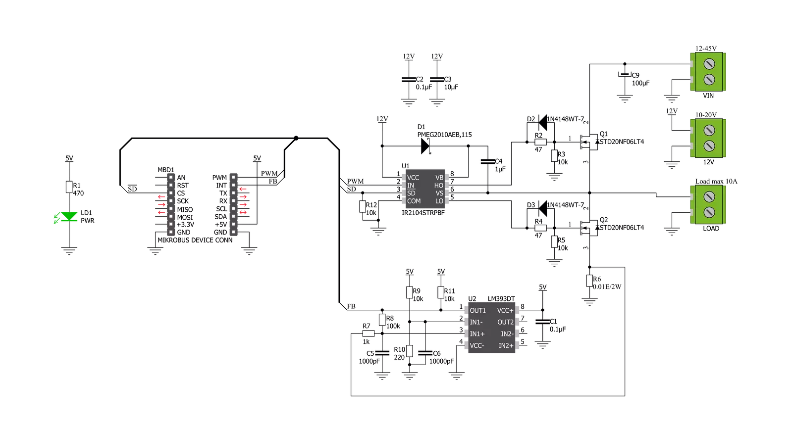
Driver 2 Click is based on the IR2104S, a high-voltage, high-speed power MOSFET and IGBT driver with typical 0.21A source and 0.36A sink currents and independent high and low side referenced output channels from Infineon Technologies. A gate driver IR2104S represents a power amplifier that accepts a low-power input from a controller IC and produces a high-current drive input for the gate of a high-power transistor such as a power MOSFET. In essence, it consists of a level shifter in combination with an amplifier. It has many applications, ranging from the DC-DC power supply for high power density and efficiency to a wide range of motor applications such as home appliances, industrial drives, DC brushed and brushless motors, and more. This Click board™ has a logic input compatible with standard CMOS or LSTTL outputs, down to 3.3V logic, and features the additional Shutdown function. The output drivers feature a high pulse current buffer
stage designed for minimum driver cross-conduction. It also possesses a precision voltage comparator, the LM393, with input offset voltage specifications as low as 2.0 mV built to permit a common-mode range–to–ground level with single supply operation from STMicroelectronics. In combination with the INT pin, with the help of this comparator, we can get feedback in case of exceeding the maximum current value on the LOAD terminal (over-current detection). Driver 2 Click operates with the PWM signal that drives the input IN pin of the IR2104S and communicates with MCU with two other pins routed on the INT and CS pins of the mikroBUS™ socket labeled as FB and SD. This Click board™ possesses three connectors, one representing an external power supply labeled as VIN in the range from 12 to 45V. The next one is the gate-driver power supply terminal with a fixed voltage value of 12V, and the last terminal labeled as LOAD is a
terminal that can supply the load with a maximum current of up to 10A. As mentioned before, additional functionality is two pins routed on the CS and INT pins of the mikroBUS™ socket. A signal on the CS pin labeled as SD represents a Shutdown function able to turn off both channels of the IR2104S, while another pin, INT, marked as the FB is an indication, more accurately an interrupt, to the MCU if the maximum value of the output current is exceeded. This Click board™ can only be operated with a 5V logic voltage level. The board must perform appropriate logic voltage level conversion before using MCUs with different logic levels. However, the Click board™ comes equipped with a library containing functions and an example code that can be used as a reference for further development.

Features overview
Development board
Discovery kit with STM32F407VG MCU, powered by the STM32F407 microcontroller, simplifies audio application development. It offers a robust platform with features like the ST-LINK/V2-A debugger, STMEMS digital accelerometer, digital microphone, and integrated audio DAC with a class D speaker driver. It has LEDs, push buttons, and a USB OTG
Micro-AB connector for versatile connectivity. The STM32F407VGT6 MCU boasts a 32-bit Arm Cortex-M4 with FPU, 1MB Flash memory, and 192KB RAM, housed in an LQFP100 package. Equipped with USB OTG FS, MEMS accelerometer, omnidirectional digital microphone, and user-friendly buttons, it ensures seamless operation.
The board accommodates various add-ons via extension headers while offering flexible power supply options, including ST-LINK, USB VBUS, or external sources. Supported by comprehensive free software and a range of IDEs, it empowers developers with flexibility and ease of use, making it an ideal choice for audio-centric projects.

Microcontroller Overview
MCU Card / MCU

Architecture
ARM Cortex-M4
MCU Memory (KB)
10
Silicon Vendor
STMicroelectronics
Pin count
100
RAM (Bytes)
100
You complete me!
Accessories
STM32F4 Discovery Shield is the perfect extension for your STM32F4 Discovery Board from STMicroelectronics. This versatile shield features four mikroBUS™ host sockets, a USB-UART module, and a CAN transceiver, expanding the capabilities of your Discovery board. Acting as a docking station, the STM32F4 Discovery Shield enables you to effortlessly transform your board into various applications, whether it's an RFID lock, SMS-triggered control switch, GPS tracking device, full-blown weather station, or any other idea you have in mind. With its seamless integration and enhanced functionality, this shield empowers you to explore endless possibilities and quickly bring your projects to life.

DC Gear Motor - 430RPM (3-6V) represents an all-in-one combination of a motor and gearbox, where the addition of gear leads to a reduction of motor speed while increasing the torque output. This gear motor has a spur gearbox, making it a highly reliable solution for applications with lower torque and speed requirements. The most critical parameters for gear motors are speed, torque, and efficiency, which are, in this case, 520RPM with no load and 430RPM at maximum efficiency, alongside a current of 60mA and a torque of 50g.cm. Rated for a 3-6V operational voltage range and clockwise/counterclockwise rotation direction, this motor represents an excellent solution for many functions initially performed by brushed DC motors in robotics, medical equipment, electric door locks, and much more.

Used MCU Pins
mikroBUS™ mapper
Take a closer look
Click board™ Schematic
Step by step
Project assembly

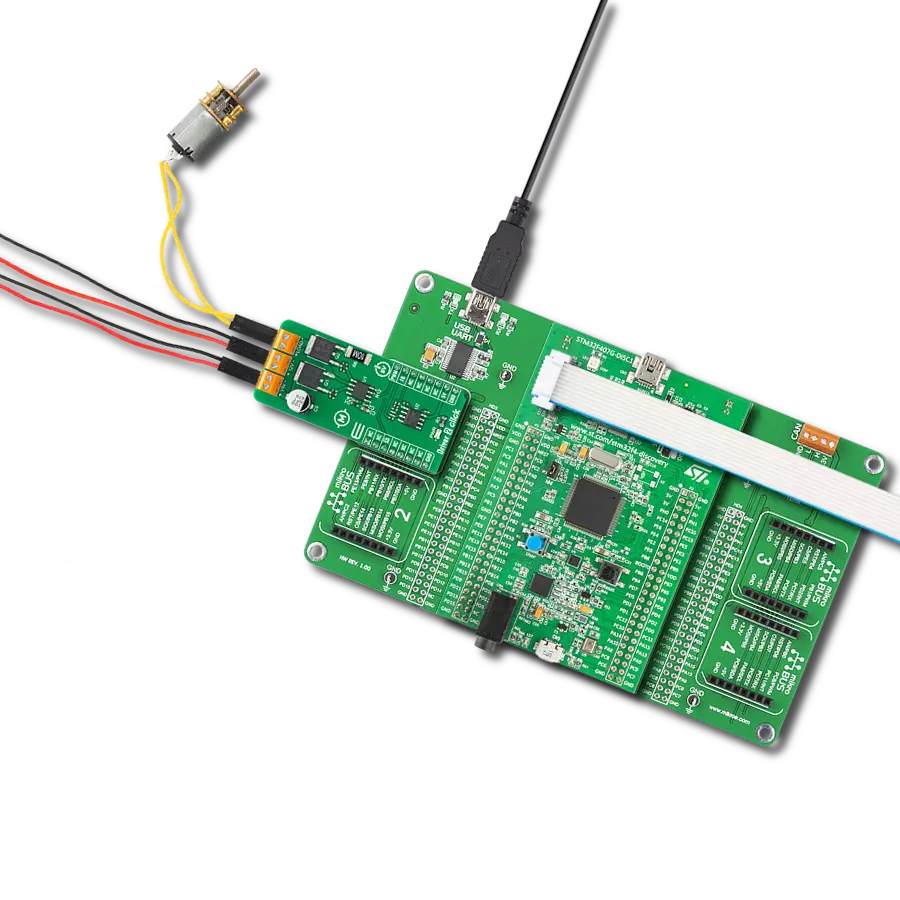
Start by selecting your development board and Click board™. Begin with the Discovery kit with STM32F407VG MCU as your development board.


Software Support
Library Description
This library contains API for Driver 2 Click driver.
Key functions:
void driver2_set_sd_pin ( uint8_t state )- Set SD pinvoid driver2_set_pwm_pin ( uint8_t state )- Set PWM pinuint8_t driver2_get_fb_pin ( void )- Get FB pin
Open Source
Code example
The complete application code and a ready-to-use project are available through the NECTO Studio Package Manager for direct installation in the NECTO Studio. The application code can also be found on the MIKROE GitHub account.
/*!
 * @file main.c
 * @brief Driver2 Click example
 *
 * # Description
 * This is an example that demonstrates the use of the Driver 2 Click board.
 *
 * The demo application is composed of two sections :
 *
 * ## Application Init
 * Initializes driver module and sets PWM.
 *
 * ## Application Task
 * Start motor example with change in motor speed using changes in PWM duty cycle.
 *
 *
 * @author Stefan Ilic
 *
 */

#include "board.h"
#include "log.h"
#include "driver2.h"

static driver2_t driver2;
static log_t logger;

void application_init ( void ) {
    log_cfg_t log_cfg;  /**< Logger config object. */
    driver2_cfg_t driver2_cfg;  /**< Click config object. */

    /**
     * Logger initialization.
     * Default baud rate: 115200
     * Default log level: LOG_LEVEL_DEBUG
     * @note If USB_UART_RX and USB_UART_TX
     * are defined as HAL_PIN_NC, you will
     * need to define them manually for log to work.
     * See @b LOG_MAP_USB_UART macro definition for detailed explanation.
     */
    LOG_MAP_USB_UART( log_cfg );
    log_init( &logger, &log_cfg );
    log_info( &logger, " Application Init " );

    // Click initialization.

    driver2_cfg_setup( &driver2_cfg );
    DRIVER2_MAP_MIKROBUS( driver2_cfg, MIKROBUS_1 );
    err_t init_flag  = driver2_init( &driver2, &driver2_cfg );
    if ( PWM_ERROR == init_flag ) {
        log_error( &logger, " Application Init Error. " );
        log_info( &logger, " Please, run program again... " );

        for ( ; ; );
    }

    driver2_default_cfg ( &driver2 );

    driver2_set_duty_cycle ( &driver2, 0.0 );
    driver2_pwm_start( &driver2 );

    log_info( &logger, " Application Task " );
}

void application_task ( void ) {
    static int8_t duty_cnt = 1;
    static int8_t duty_inc = 1;
    float duty = duty_cnt / 10.0;

    driver2_set_duty_cycle ( &driver2, duty );
    log_printf( &logger, "> Duty: %d%%\r\n", ( uint16_t )( duty_cnt * 10 ) );

    Delay_ms ( 500 );

    if ( 10 == duty_cnt ) {
        duty_inc = -1;
    } else if ( 0 == duty_cnt ) {
        duty_inc = 1;
    }
    duty_cnt += duty_inc;
}

int main ( void )
{
    /* Do not remove this line or clock might not be set correctly. */
    #ifdef PREINIT_SUPPORTED
    preinit();
    #endif

    application_init( );

    for ( ; ; )
    {
        application_task( );
    }

    return 0;
}

// ------------------------------------------------------------------------ END
Additional Support
Resources
Category:Brushed


