Attain precise data on the amount of current flowing through a circuit with the ACS37600K and STM32L496ZG
Programmable linear Hall-effect sensor for core-based current sensing

Published Aug 22, 2024
Click board™
Current 11 Click
Dev. board
Nucleo-144 with STM32L496ZG MCU
Compiler
NECTO Studio
MCU
STM32L496ZG
Measure output current for load monitoring and power supply regulation
A
A
Hardware Overview
How does it work?
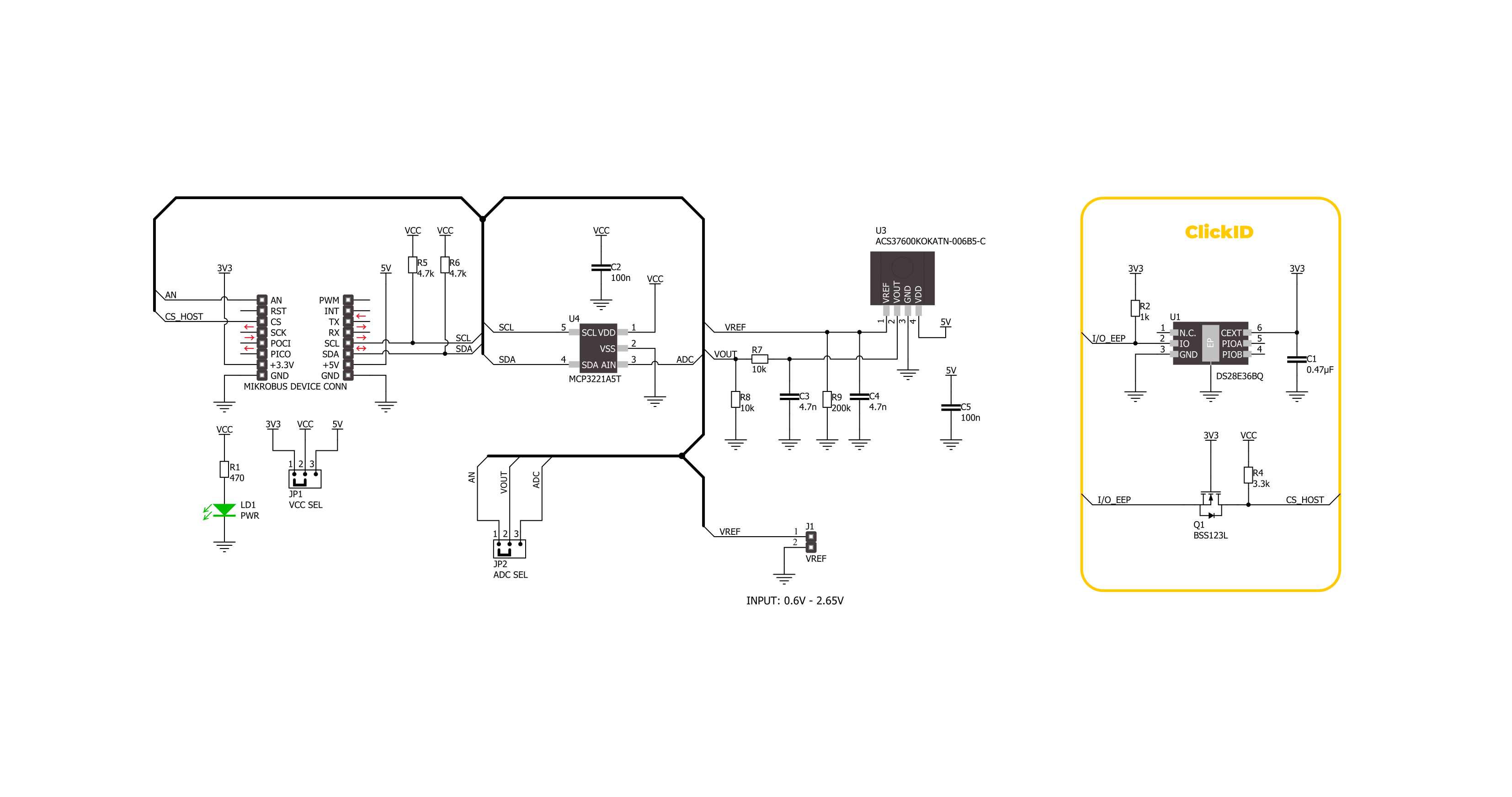
Current 11 Click is based on the ACS37600K (ACS37600KOKATN-006B5-C), a high-precision, programmable linear Hall-effect sensor IC from Allegro Microsystems. The ACS37600K includes a highly accurate, low-offset, chopper-stabilized Hall-effect front end, which detects magnetic flux perpendicular to the IC package surface and converts it into a proportional voltage. This Click board™ is designed to be paired with a ferromagnetic core, creating an exceptionally accurate current sensor ideal for various industrial, commercial, and communication applications. It excels in current sensing modules, motor control systems, Uninterruptible Power Supplies (UPS), overcurrent detection, power supplies, and more.
The ACS37600K allows for customer-specific programming of sensitivity and offset post-manufacturing, as well as temperature-dependent sensitivity adjustments to counteract ferromagnetic core drift. With a sensitivity of 6mV/G and a bidirectional operating range of ±333G, it ensures industry-leading accuracy in current sensing applications. Moreover, it offers a user-programmable bidirectional reference voltage pin on an unpopulated VREF header, in a range from 0.6V up to 2.65V, that continuously monitors the zero-current voltage, enhancing the sensor's reliability and precision. The output signal of the ACS37600K can be converted to a digital value using MCP3221, a successive approximation A/D
converter with a 12-bit resolution from Microchip using a 2-wire I2C compatible interface, or can be sent directly to an analog pin of the mikroBUS™ socket labeled as AN. Selection can be performed via an onboard SMD jumper labeled ADC SEL, placing it in an appropriate position marked as AN and ADC. This Click board™ can operate with either 3.3V or 5V logic voltage levels selected via the VCC SEL jumper. This way, both 3.3V and 5V capable MCUs can use the communication lines properly. Also, this Click board™ comes equipped with a library containing easy-to-use functions and an example code that can be used as a reference for further development.

Features overview
Development board
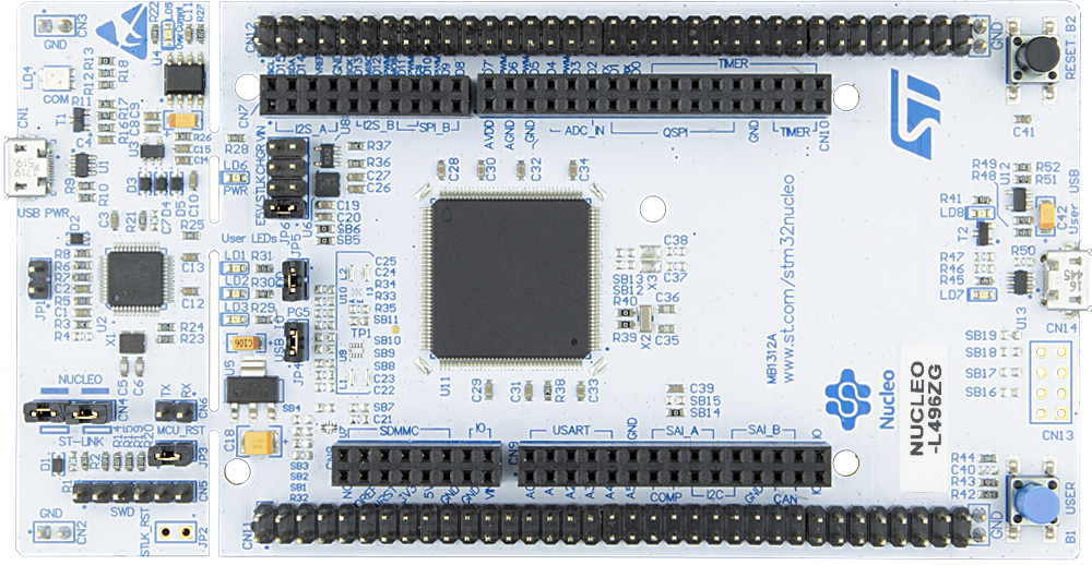
Nucleo-144 with STM32L496ZG MCU board offers an accessible and adaptable avenue for users to explore new ideas and construct prototypes. It allows users to tailor their experience by selecting from a range of performance and power consumption features offered by the STM32 microcontroller. With compatible boards, the
internal or external SMPS dramatically decreases power usage in Run mode. Including the ST Zio connector, expanding ARDUINO Uno V3 connectivity, and ST morpho headers facilitate easy expansion of the Nucleo open development platform. The integrated ST-LINK debugger/programmer enhances convenience by
eliminating the need for a separate probe. Moreover, the board is accompanied by comprehensive free software libraries and examples within the STM32Cube MCU Package, further enhancing its utility and value.

Microcontroller Overview
MCU Card / MCU
Architecture
ARM Cortex-M4
MCU Memory (KB)
1024
Silicon Vendor
STMicroelectronics
Pin count
144
RAM (Bytes)
327680
You complete me!
Accessories
Click Shield for Nucleo-144 comes equipped with four mikroBUS™ sockets, with one in the form of a Shuttle connector, allowing all the Click board™ devices to be interfaced with the STM32 Nucleo-144 board with no effort. This way, MIKROE allows its users to add any functionality from our ever-growing range of Click boards™, such as WiFi, GSM, GPS, Bluetooth, ZigBee, environmental sensors, LEDs, speech recognition, motor control, movement sensors, and many more. Featuring an ARM Cortex-M microcontroller, 144 pins, and Arduino™ compatibility, the STM32 Nucleo-144 board offers limitless possibilities for prototyping and creating diverse applications. These boards are controlled and powered conveniently through a USB connection to program and efficiently debug the Nucleo-144 board out of the box, with an additional USB cable connected to the USB mini port on the board. Simplify your project development with the integrated ST-Link debugger and unleash creativity using the extensive I/O options and expansion capabilities. This Click Shield also has several switches that perform functions such as selecting the logic levels of analog signals on mikroBUS™ sockets and selecting logic voltage levels of the mikroBUS™ sockets themselves. Besides, the user is offered the possibility of using any Click board™ with the help of existing bidirectional level-shifting voltage translators, regardless of whether the Click board™ operates at a 3.3V or 5V logic voltage level. Once you connect the STM32 Nucleo-144 board with our Click Shield for Nucleo-144, you can access hundreds of Click boards™, working with 3.3V or 5V logic voltage levels.

Used MCU Pins
mikroBUS™ mapper
Take a closer look
Click board™ Schematic
Step by step
Project assembly
Start by selecting your development board and Click board™. Begin with the Nucleo-144 with STM32L496ZG MCU as your development board.


Track your results in real time
Application Output
1. Application Output - In Debug mode, the 'Application Output' window enables real-time data monitoring, offering direct insight into execution results. Ensure proper data display by configuring the environment correctly using the provided tutorial.

2. UART Terminal - Use the UART Terminal to monitor data transmission via a USB to UART converter, allowing direct communication between the Click board™ and your development system. Configure the baud rate and other serial settings according to your project's requirements to ensure proper functionality. For step-by-step setup instructions, refer to the provided tutorial.

3. Plot Output - The Plot feature offers a powerful way to visualize real-time sensor data, enabling trend analysis, debugging, and comparison of multiple data points. To set it up correctly, follow the provided tutorial, which includes a step-by-step example of using the Plot feature to display Click board™ readings. To use the Plot feature in your code, use the function: plot(*insert_graph_name*, variable_name);. This is a general format, and it is up to the user to replace 'insert_graph_name' with the actual graph name and 'variable_name' with the parameter to be displayed.

Software Support
Library Description
This library contains API for Current 11 Click driver.
Key functions:
current11_set_vref- This function sets the voltage reference for Current 11 click driver.current11_calibrate_offset- This function calibrates the zero current offset value.current11_read_current- This function reads the input current level [A] based on CURRENT11_NUM_CONVERSIONS of voltage measurements.
Open Source
Code example
The complete application code and a ready-to-use project are available through the NECTO Studio Package Manager for direct installation in the NECTO Studio. The application code can also be found on the MIKROE GitHub account.
/*!
* @file main.c
* @brief Current 11 Click Example.
*
* # Description
* This example demonstrates the use of Current 11 Click board by reading and
* displaying the input current measurements.
*
* The demo application is composed of two sections :
*
* ## Application Init
* Initializes the driver and calibrates the zero current offset.
*
* ## Application Task
* Reads the input current measurements and displays the results on the USB UART
* approximately once per second.
*
* @note
* For better accuracy, set the voltage reference by using the @b current11_set_vref function,
* increase the number of conversions by modifying the @b CURRENT11_NUM_CONVERSIONS macro,
* and adjust the @b CURRENT11_COUPLING_FACTOR_G_A value.
*
* @author Stefan Filipovic
*
*/
#include "board.h"
#include "log.h"
#include "current11.h"
static current11_t current11; /**< Current 11 Click driver object. */
static log_t logger; /**< Logger object. */
void application_init ( void )
{
log_cfg_t log_cfg; /**< Logger config object. */
current11_cfg_t current11_cfg; /**< Click config object. */
/**
* Logger initialization.
* Default baud rate: 115200
* Default log level: LOG_LEVEL_DEBUG
* @note If USB_UART_RX and USB_UART_TX
* are defined as HAL_PIN_NC, you will
* need to define them manually for log to work.
* See @b LOG_MAP_USB_UART macro definition for detailed explanation.
*/
LOG_MAP_USB_UART( log_cfg );
log_init( &logger, &log_cfg );
log_info( &logger, " Application Init " );
// Click initialization.
current11_cfg_setup( ¤t11_cfg );
CURRENT11_MAP_MIKROBUS( current11_cfg, MIKROBUS_1 );
err_t init_flag = current11_init( ¤t11, ¤t11_cfg );
if ( ( ADC_ERROR == init_flag ) || ( I2C_MASTER_ERROR == init_flag ) )
{
log_error( &logger, " Communication init." );
for ( ; ; );
}
log_printf( &logger, " Calibrating zero current offset in 5 seconds...\r\n" );
log_printf( &logger, " Make sure no current flows through the sensor during the calibration process.\r\n" );
Delay_ms ( 1000 );
Delay_ms ( 1000 );
Delay_ms ( 1000 );
Delay_ms ( 1000 );
Delay_ms ( 1000 );
if ( CURRENT11_ERROR == current11_calibrate_offset ( ¤t11 ) )
{
log_error( &logger, " Calibrate offset." );
for ( ; ; );
}
log_printf( &logger, " Calibration DONE.\r\n" );
log_info( &logger, " Application Task " );
}
void application_task ( void )
{
float current = 0;
if ( CURRENT11_OK == current11_read_current ( ¤t11, ¤t ) )
{
log_printf( &logger, " Current : %.1f A\r\n\n", current );
Delay_ms ( 1000 );
}
}
int main ( void )
{
/* Do not remove this line or clock might not be set correctly. */
#ifdef PREINIT_SUPPORTED
preinit();
#endif
application_init( );
for ( ; ; )
{
application_task( );
}
return 0;
}
// ------------------------------------------------------------------------ END
Additional Support
Resources
Category:Current sensor


