Achieve precise color detection and customization with ISL29125 and STM32F413ZH in various applications
Unveiling the spectrum
Published Feb 14, 2024
Click board™
Color 2 Click
Dev. board
Nucleo 144 with STM32F413ZH MCU
Compiler
NECTO Studio
MCU
STM32F413ZH
Discover how this innovative RGB color sensing solution opens up a world of possibilities, enabling you to accurately capture and analyze colors for a multitude of applications
A
A
Hardware Overview
How does it work?
Color 2 Click is based on the ISL29125, a low power, high sensitivity, red, green, and blue color light sensor (RGB) with a compatible I2C interface from Renesas. The ISL29125’s state-of-the-art photodiode array provides an accurate RGB spectral response and excellent light source-to-light source variation, designed to reject IR in light sources, allowing the device to operate in environments from sunlight to dark rooms. It detects red, green, and blue in various lighting conditions, outputting high-resolution data in a measuring range from 0.152 lux to 10,000 lux. Both the range and output resolution are selectable through an I2C interface. After light is converted to the current during the light-to-signal process, the current output is converted to a digital count by
an on-chip analog-to-digital converter with an integrating architecture. The ADC converter resolution is selectable from 12 or 16 bits, with its conversion time inversely proportional to the ADC resolution. The ADC also provides two programmable ranges to accommodate different lighting conditions dynamically. For dim conditions, the ADC can be configured at its high sensitivity (low optical) range, while for bright conditions, it can be configured at its low sensitivity (higher optical) range. The ISL29125 also incorporates an IR blocking filter, allowing this Click board™ to operate even under a dark glass cover. This Click board™ communicates with MCU using the standard I2C 2-Wire interface to read data and configure settings, supporting a Fast
Mode up to 400kHz. Besides, it also possesses an interrupt feature, routed to the INT pin of the mikroBUS™ socket, which serves as an alarm or monitoring function to determine whether the ambient light level exceeds the upper threshold or goes below the lower threshold. The user can also configure the persistency of the interrupt pin, which reduces the possibility of false triggers, such as noise or sudden spikes in ambient light conditions. This Click board™ can be operated only with a 3.3V logic voltage level. The board must perform appropriate logic voltage level conversion before using MCUs with different logic levels. Also, it comes equipped with a library containing functions and an example code that can be used as a reference for further development.

Features overview
Development board
Nucleo-144 with STM32F413ZH MCU board offers an accessible and adaptable avenue for users to explore new ideas and construct prototypes. It allows users to tailor their experience by selecting from a range of performance and power consumption features offered by the STM32 microcontroller. With compatible boards, the
internal or external SMPS dramatically decreases power usage in Run mode. Including the ST Zio connector, expanding ARDUINO Uno V3 connectivity, and ST morpho headers facilitate easy expansion of the Nucleo open development platform. The integrated ST-LINK debugger/programmer enhances convenience by
eliminating the need for a separate probe. Moreover, the board is accompanied by comprehensive free software libraries and examples within the STM32Cube MCU Package, further enhancing its utility and value.

Microcontroller Overview
MCU Card / MCU

Architecture
ARM Cortex-M4
MCU Memory (KB)
1536
Silicon Vendor
STMicroelectronics
Pin count
144
RAM (Bytes)
327680
You complete me!
Accessories
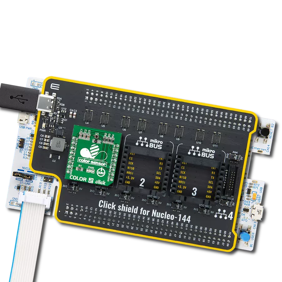
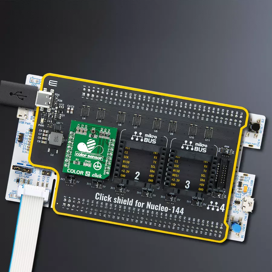
Click Shield for Nucleo-144 comes equipped with four mikroBUS™ sockets, with one in the form of a Shuttle connector, allowing all the Click board™ devices to be interfaced with the STM32 Nucleo-144 board with no effort. This way, MIKROE allows its users to add any functionality from our ever-growing range of Click boards™, such as WiFi, GSM, GPS, Bluetooth, ZigBee, environmental sensors, LEDs, speech recognition, motor control, movement sensors, and many more. Featuring an ARM Cortex-M microcontroller, 144 pins, and Arduino™ compatibility, the STM32 Nucleo-144 board offers limitless possibilities for prototyping and creating diverse applications. These boards are controlled and powered conveniently through a USB connection to program and efficiently debug the Nucleo-144 board out of the box, with an additional USB cable connected to the USB mini port on the board. Simplify your project development with the integrated ST-Link debugger and unleash creativity using the extensive I/O options and expansion capabilities. This Click Shield also has several switches that perform functions such as selecting the logic levels of analog signals on mikroBUS™ sockets and selecting logic voltage levels of the mikroBUS™ sockets themselves. Besides, the user is offered the possibility of using any Click board™ with the help of existing bidirectional level-shifting voltage translators, regardless of whether the Click board™ operates at a 3.3V or 5V logic voltage level. Once you connect the STM32 Nucleo-144 board with our Click Shield for Nucleo-144, you can access hundreds of Click boards™, working with 3.3V or 5V logic voltage levels.

Used MCU Pins
mikroBUS™ mapper
Take a closer look
Click board™ Schematic

Step by step
Project assembly
Start by selecting your development board and Click board™. Begin with the Nucleo 144 with STM32F413ZH MCU as your development board.


Track your results in real time
Application Output
1. Application Output - In Debug mode, the 'Application Output' window enables real-time data monitoring, offering direct insight into execution results. Ensure proper data display by configuring the environment correctly using the provided tutorial.

2. UART Terminal - Use the UART Terminal to monitor data transmission via a USB to UART converter, allowing direct communication between the Click board™ and your development system. Configure the baud rate and other serial settings according to your project's requirements to ensure proper functionality. For step-by-step setup instructions, refer to the provided tutorial.

3. Plot Output - The Plot feature offers a powerful way to visualize real-time sensor data, enabling trend analysis, debugging, and comparison of multiple data points. To set it up correctly, follow the provided tutorial, which includes a step-by-step example of using the Plot feature to display Click board™ readings. To use the Plot feature in your code, use the function: plot(*insert_graph_name*, variable_name);. This is a general format, and it is up to the user to replace 'insert_graph_name' with the actual graph name and 'variable_name' with the parameter to be displayed.

Software Support
Library Description
This library contains API for Color 2 Click driver.
Key functions:
color2_read_rgb- Function read red, green, and blue data from ISL29125color2_rgb_to_hsl- This function converts RGB (red, green, blue) to HSL (hue, saturation, lightness) color valuecolor2_get_color- This function returns the color name flag from the input HSL color
Open Source
Code example
The complete application code and a ready-to-use project are available through the NECTO Studio Package Manager for direct installation in the NECTO Studio. The application code can also be found on the MIKROE GitHub account.
/*!
 * \file
 * \brief Color 2 Click example
 *
 * # Description
 * This example demonstrates the use of Color 2 Click board by reading data
 * from RGB channels and converting them to HSL color and displaying those data as
 * well as the detected color name on the USB UART.
 *
 * The demo application is composed of two sections :
 *
 * ## Application Init
 * Initializes the driver and performs the Click default configuration.
 *
 * ## Application Task
 * Waits for the data ready interrupt, then reads the values of all channels and converts
 * them to HSL color and displays those data as well as the detected color name on the USB UART
 * every 100ms approximately.
 *
 * \author MikroE Team
 *
 */
// ------------------------------------------------------------------- INCLUDES

#include "board.h"
#include "log.h"
#include "color2.h"

// ------------------------------------------------------------------ VARIABLES

static color2_t color2;
static log_t logger;

// ------------------------------------------------------ APPLICATION FUNCTIONS

void application_init ( void )
{
    log_cfg_t log_cfg;
    color2_cfg_t cfg;

    /**
     * Logger initialization.
     * Default baud rate: 115200
     * Default log level: LOG_LEVEL_DEBUG
     * @note If USB_UART_RX and USB_UART_TX
     * are defined as HAL_PIN_NC, you will
     * need to define them manually for log to work.
     * See @b LOG_MAP_USB_UART macro definition for detailed explanation.
     */
    LOG_MAP_USB_UART( log_cfg );
    log_init( &logger, &log_cfg );
    log_info( &logger, "---- Application Init ----" );

    //  Click initialization.
    color2_cfg_setup( &cfg );
    COLOR2_MAP_MIKROBUS( cfg, MIKROBUS_1 );
    color2_init( &color2, &cfg );

    if ( COLOR2_ERROR == color2_default_cfg ( &color2 ) )
    {
        log_error( &logger, " Default configuration." );
        for ( ; ; );
    }
    log_info( &logger, " Application Task " );
}

void application_task ( void )
{
    // Wait for the data ready interrupt indication
    while ( color2_get_int_pin ( &color2 ) );

    uint8_t status = 0;
    color2_rgb_t rgb;
    if ( ( COLOR2_OK == color2_read_status ( &color2, &status ) ) &&
         ( COLOR2_OK == color2_read_rgb ( &color2, &rgb ) ) )
    {
        color2_hsl_t hsl;
        color2_rgb_to_hsl ( &color2, &rgb, &hsl );
        log_printf ( &logger, "\r\n Red: %u\r\n", rgb.red );
        log_printf ( &logger, " Green: %u\r\n", rgb.green );
        log_printf ( &logger, " Blue: %u\r\n", rgb.blue );
        log_printf ( &logger, " Hue: %.1f deg\r\n", hsl.hue );
        log_printf ( &logger, " Saturation: %.1f %%\r\n", hsl.saturation );
        log_printf ( &logger, " Lightness: %.1f %%\r\n", hsl.lightness );
        log_printf ( &logger, " Dominated color: " );
        switch ( color2_get_color ( &hsl ) )
        {
            case COLOR2_RED_COLOR:
            {
                log_printf ( &logger, "RED\r\n" );
                break;
            }
            case COLOR2_YELLOW_COLOR:
            {
                log_printf ( &logger, "YELLOW\r\n" );
                break;
            }
            case COLOR2_GREEN_COLOR:
            {
                log_printf ( &logger, "GREEN\r\n" );
                break;
            }
            case COLOR2_CYAN_COLOR:
            {
                log_printf ( &logger, "CYAN\r\n" );
                break;
            }
            case COLOR2_BLUE_COLOR:
            {
                log_printf ( &logger, "BLUE\r\n" );
                break;
            }
            case COLOR2_MAGENTA_COLOR:
            {
                log_printf ( &logger, "MAGENTA\r\n" );
                break;
            }
            case COLOR2_WHITE_COLOR:
            {
                log_printf ( &logger, "WHITE\r\n" );
                break;
            }
            case COLOR2_BLACK_COLOR:
            {
                log_printf ( &logger, "BLACK\r\n" );
                break;
            }
            default:
            {
                log_printf ( &logger, "UNKNOWN\r\n" );
                break;
            }
        }
    }
}

int main ( void )
{
    /* Do not remove this line or clock might not be set correctly. */
    #ifdef PREINIT_SUPPORTED
    preinit();
    #endif

    application_init( );

    for ( ; ; )
    {
        application_task( );
    }

    return 0;
}


// ------------------------------------------------------------------------ END


