Upgrade your projects with all-in-one sensing solution based on the IQS621 and STM32F413ZH
Sensory fusion: touch, magnetism, and beyond!
Published Feb 14, 2024
Click board™
ProxFusion 2 Click
Dev. board
Nucleo 144 with STM32F413ZH MCU
Compiler
NECTO Studio
MCU
STM32F413ZH
Our groundbreaking solution, combining capacitive touch, Hall-effect, and inductance sensing capabilities, aims to provide a comprehensive and versatile sensing platform that opens the door to a myriad of applications across various industries
A
A
Hardware Overview
How does it work?
ProxFusion 2 Click is based on the IQS621, a multifunctional sensor with ambient light (ALS), capacitive touch, Hall-effect, and inductance sensing capabilities, from Azoteq. Their IQ Switch® ProxFusion® sensor series is one of the first to incorporate several sensory functions on the same die. This makes the IQS62x series perfectly suited for compact designs, such as those used in IoT or various home automation systems. The IQS621 IC does not sacrifice any feature in favor of having multiple sensors on the same chip; on the contrary, it offers all the key features commonly found on other stand-alone sensors. The sensitivity of IQS621 is improved by using a regulated and stable internal power supply, along with the Automatic Tuning Implementation (ATI) technology, which provides consistent readings, regardless of environmental conditions. The capacitive sensor is based on the proven ProxSense® technology. It allows self-capacitance sensing, adjustable proximity and touch thresholds, alternative ATI modes, and individual sensitivity setups. The IQS621 offers two distinctive user interfaces that can be used with the capacitive sensor: Discrete Button UI and Hysteresis UI. Both interfaces offer programmable registers to set up the sensing parameters, such as
thresholds, filter settings, ATI settings, and more. While the Discrete prox/touch UI is more suited to be used as the ON/OFF switch detector, the Hysteresis UI can program sensing of more complex events. An inductive sensor is also present on this IC. It can be used to detect the presence of metal objects. Again, two distinct user interfaces are available, each with its own set of registers. There is a Discrete Button UI, as well as the Hysteresis UI. The detection thresholds are widely adjustable, allowing reliable detection of even smaller metallic objects. ProxFusion® 2 click has the PCB trace coil area, which allows inductive detection. The same area of the Click board™ is used to sense capacitive events. The IQS621 also features an ambient light sensor (ALS). The ALS UI outputs readings directly in Lux, requiring no additional conversion. The ALS response is calibrated according to the human eye. It also features an IR filter, reducing the influence of infrared light. The ALS includes a selectable range and two threshold settings for day/night indication. ALS enables the design of smart light switches: detecting night/day events might be used to regulate the lighting, for example. Hall-effect sensors can be used to detect changes in the magnetic field. Unlike the capacitive and
inductive sensors, the Hall sensor requires no external parts since Hall plates are embedded into the IC. Hall-sensor allows several events to be detected, as an advanced signal processing algorithm supports it. Besides other features, it can detect field pole orientation (N/S), allowing it to be used as a switch. This allows it to be used for different kinds of contactless HMIs. A temperature sensor is one of the most commonly used sensors. It can be found even on other sensors, such as pressure or humidity, since the temperature affects readings. The role of the thermal sensor in IQS621 is no different: it is used to provide a calibration base for other sensors on this IC. However, this sensor can also monitor the ambient temperature in any application. Finally, each detected ON/OFF type event can be monitored in the Global events register. This is very useful as the host MCU can only poll a few registers to discover these events. The communication with the IQS621 is done over the I2C interface with the additional RDY pin. This pin is routed to the INT pin of the mikroBUS™ and indicates a communications window. The Click board™ is designed to work with 3.3V only. A proper level translation circuit should be used when using it with MCUs that use 5V levels for their communication.


Features overview
Development board
Nucleo-144 with STM32F413ZH MCU board offers an accessible and adaptable avenue for users to explore new ideas and construct prototypes. It allows users to tailor their experience by selecting from a range of performance and power consumption features offered by the STM32 microcontroller. With compatible boards, the
internal or external SMPS dramatically decreases power usage in Run mode. Including the ST Zio connector, expanding ARDUINO Uno V3 connectivity, and ST morpho headers facilitate easy expansion of the Nucleo open development platform. The integrated ST-LINK debugger/programmer enhances convenience by
eliminating the need for a separate probe. Moreover, the board is accompanied by comprehensive free software libraries and examples within the STM32Cube MCU Package, further enhancing its utility and value.

Microcontroller Overview
MCU Card / MCU

Architecture
ARM Cortex-M4
MCU Memory (KB)
1536
Silicon Vendor
STMicroelectronics
Pin count
144
RAM (Bytes)
327680
You complete me!
Accessories
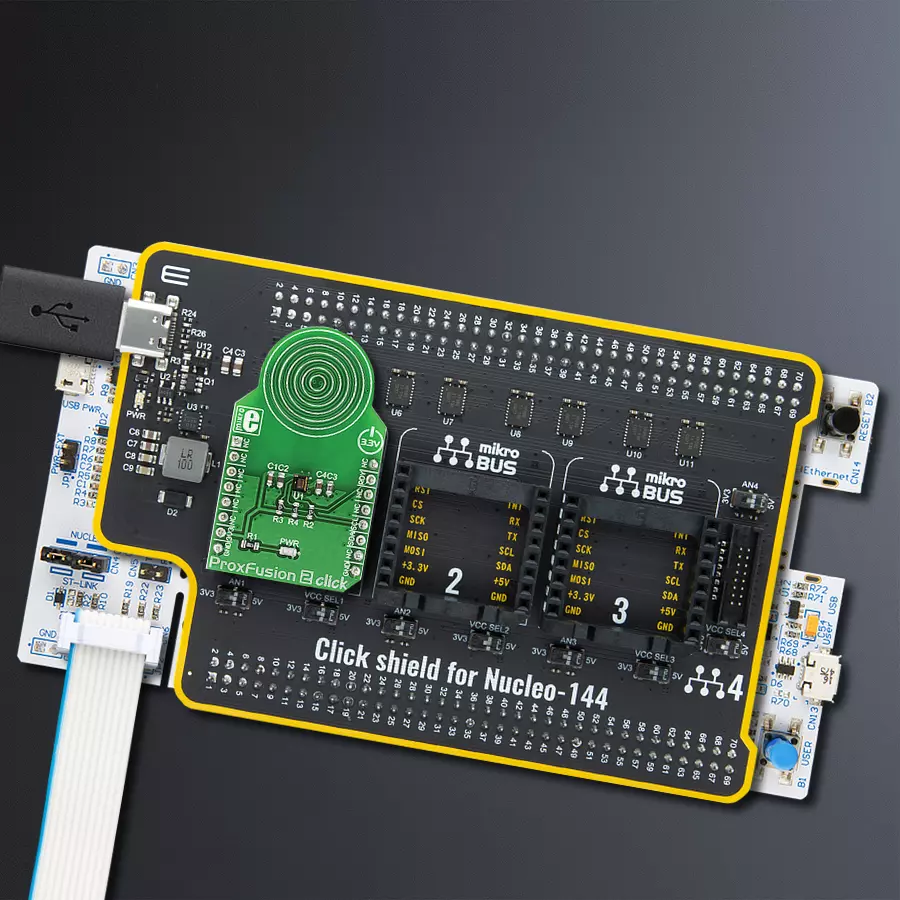
Click Shield for Nucleo-144 comes equipped with four mikroBUS™ sockets, with one in the form of a Shuttle connector, allowing all the Click board™ devices to be interfaced with the STM32 Nucleo-144 board with no effort. This way, MIKROE allows its users to add any functionality from our ever-growing range of Click boards™, such as WiFi, GSM, GPS, Bluetooth, ZigBee, environmental sensors, LEDs, speech recognition, motor control, movement sensors, and many more. Featuring an ARM Cortex-M microcontroller, 144 pins, and Arduino™ compatibility, the STM32 Nucleo-144 board offers limitless possibilities for prototyping and creating diverse applications. These boards are controlled and powered conveniently through a USB connection to program and efficiently debug the Nucleo-144 board out of the box, with an additional USB cable connected to the USB mini port on the board. Simplify your project development with the integrated ST-Link debugger and unleash creativity using the extensive I/O options and expansion capabilities. This Click Shield also has several switches that perform functions such as selecting the logic levels of analog signals on mikroBUS™ sockets and selecting logic voltage levels of the mikroBUS™ sockets themselves. Besides, the user is offered the possibility of using any Click board™ with the help of existing bidirectional level-shifting voltage translators, regardless of whether the Click board™ operates at a 3.3V or 5V logic voltage level. Once you connect the STM32 Nucleo-144 board with our Click Shield for Nucleo-144, you can access hundreds of Click boards™, working with 3.3V or 5V logic voltage levels.

Used MCU Pins
mikroBUS™ mapper
Take a closer look
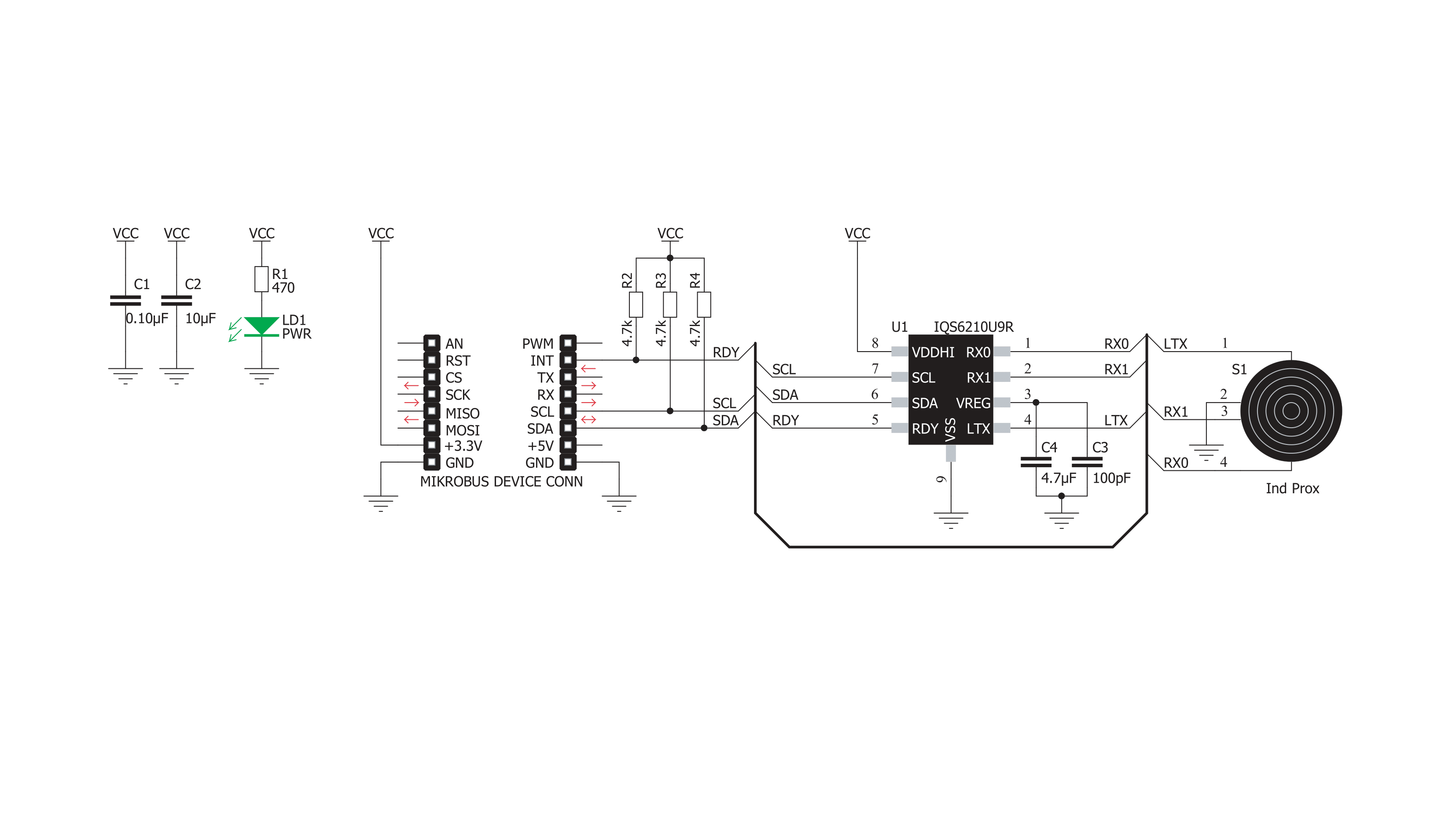
Click board™ Schematic
Step by step
Project assembly
Start by selecting your development board and Click board™. Begin with the Nucleo 144 with STM32F413ZH MCU as your development board.


Track your results in real time
Application Output
1. Application Output - In Debug mode, the 'Application Output' window enables real-time data monitoring, offering direct insight into execution results. Ensure proper data display by configuring the environment correctly using the provided tutorial.

2. UART Terminal - Use the UART Terminal to monitor data transmission via a USB to UART converter, allowing direct communication between the Click board™ and your development system. Configure the baud rate and other serial settings according to your project's requirements to ensure proper functionality. For step-by-step setup instructions, refer to the provided tutorial.

3. Plot Output - The Plot feature offers a powerful way to visualize real-time sensor data, enabling trend analysis, debugging, and comparison of multiple data points. To set it up correctly, follow the provided tutorial, which includes a step-by-step example of using the Plot feature to display Click board™ readings. To use the Plot feature in your code, use the function: plot(*insert_graph_name*, variable_name);. This is a general format, and it is up to the user to replace 'insert_graph_name' with the actual graph name and 'variable_name' with the parameter to be displayed.

Software Support
Library Description
This library contains API for ProxFusion 2 Click driver.
Key functions:
proxfusion2_detect_touch- Function for detecting touchproxfusion2_detect_dark_light- Function for read ambient lightproxfusion2_detect_hall- Function for read Hall-effect
Open Source
Code example
The complete application code and a ready-to-use project are available through the NECTO Studio Package Manager for direct installation in the NECTO Studio. The application code can also be found on the MIKROE GitHub account.
/*!
 * \file
 * \brief ProxFusion2 Click example
 *
 * # Description
 * This example demontrates the use of ProxFusion 2 Click board.
 *
 * The demo application is composed of two sections :
 *
 * ## Application Init
 * Initializes the driver and performs the Click default configuration.
 *
 * ## Application Task
 * - Checks whether Touch is detected and measures the output detection.
 * - Measures Ambient lighting - whether it's Light or Dark, ALS range and ALS output.
 * - Checks the orientation of the magnet and measures the HALL output.
 *
 * \author MikroE Team
 *
 */
// ------------------------------------------------------------------- INCLUDES

#include "board.h"
#include "log.h"
#include "proxfusion2.h"

// ------------------------------------------------------------------ VARIABLES

static proxfusion2_t proxfusion2;
static log_t logger;

// ------------------------------------------------------ APPLICATION FUNCTIONS

void application_init ( void )
{
    log_cfg_t log_cfg;  /**< Logger config object. */
    proxfusion2_cfg_t proxfusion2_cfg;  /**< Click config object. */

    /**
     * Logger initialization.
     * Default baud rate: 115200
     * Default log level: LOG_LEVEL_DEBUG
     * @note If USB_UART_RX and USB_UART_TX
     * are defined as HAL_PIN_NC, you will
     * need to define them manually for log to work.
     * See @b LOG_MAP_USB_UART macro definition for detailed explanation.
     */
    LOG_MAP_USB_UART( log_cfg );
    log_init( &logger, &log_cfg );
    log_info( &logger, " Application Init " );

    // Click initialization.
    proxfusion2_cfg_setup( &proxfusion2_cfg );
    PROXFUSION2_MAP_MIKROBUS( proxfusion2_cfg, MIKROBUS_1 );
    if ( I2C_MASTER_ERROR == proxfusion2_init( &proxfusion2, &proxfusion2_cfg ) )
    {
        log_error( &logger, " Communication init." );
        for ( ; ; );
    }

    if ( PROXFUSION2_ERROR == proxfusion2_default_cfg ( &proxfusion2 ) )
    {
        log_error( &logger, " Default configuration." );
        for ( ; ; );
    }

    log_info( &logger, " Application Task " );
}

void application_task ( void )
{
    uint8_t als_range = 0;
    uint8_t hall_detect = 0;
    uint16_t read_data = 0;
    if ( PROXFUSION2_TOUCH_DETECTED == proxfusion2_detect_touch( &proxfusion2 ) )
    {
        log_printf( &logger, " TOUCH: YES\r\n" );
    }
    else
    {
        log_printf( &logger, " TOUCH: NO\r\n" );
    }
    read_data = proxfusion2_read_data( &proxfusion2 , PROXFUSION2_HYSTERESIS_UI_OUTPUT );
    log_printf( &logger, " LEVEL: %u\r\n\n", read_data );

    if ( PROXFUSION2_AMBIENT_DARK == proxfusion2_detect_dark_light( &proxfusion2, &als_range ) )
    {
        log_printf( &logger, " AMBIENT: DARK\r\n" );
    }
    else
    {
        log_printf( &logger, " AMBIENT: LIGHT\r\n" );
    }
    log_printf( &logger, " RANGE: %u\r\n", ( uint16_t ) als_range );

    read_data = proxfusion2_read_data( &proxfusion2, PROXFUSION2_ALS_UI_OUTPUT );

    log_printf( &logger, " LEVEL: %u\r\n\n", read_data );

    hall_detect = proxfusion2_detect_hall( &proxfusion2 );
    if ( PROXFUSION2_HALL_NORTH == hall_detect )
    {
        log_printf( &logger, " HALL: NORTH\r\n" );
    }
    else if ( PROXFUSION2_HALL_SOUTH == hall_detect )
    {
        log_printf( &logger, " HALL: SOUTH\r\n" );
    }
    else
    {
        log_printf( &logger, " HALL: UNKNOWN\r\n" );
    }
    read_data = proxfusion2_read_data( &proxfusion2, PROXFUSION2_HALL_EFFECT_UI_OUTPUT );
    log_printf( &logger, " LEVEL: %u\r\n", read_data );

    log_printf( &logger, " --------------\r\n" );
    Delay_ms ( 1000 );
}

int main ( void )
{
    /* Do not remove this line or clock might not be set correctly. */
    #ifdef PREINIT_SUPPORTED
    preinit();
    #endif

    application_init( );

    for ( ; ; )
    {
        application_task( );
    }

    return 0;
}


// ------------------------------------------------------------------------ END


