Detect the strength of a magnetic field in all three dimensions with SENM3Dx and STM32F091RC
3D Hall magnetic filed sensor

Published Feb 26, 2024
Click board™
3D Hall 4 Click
Dev. board
Nucleo-64 with STM32F091RC MCU
Compiler
NECTO Studio
MCU
STM32F091RC
Achieve the acquisition of all three magnetic-field components at the same time and in the same spot
A
A
Hardware Overview
How does it work?
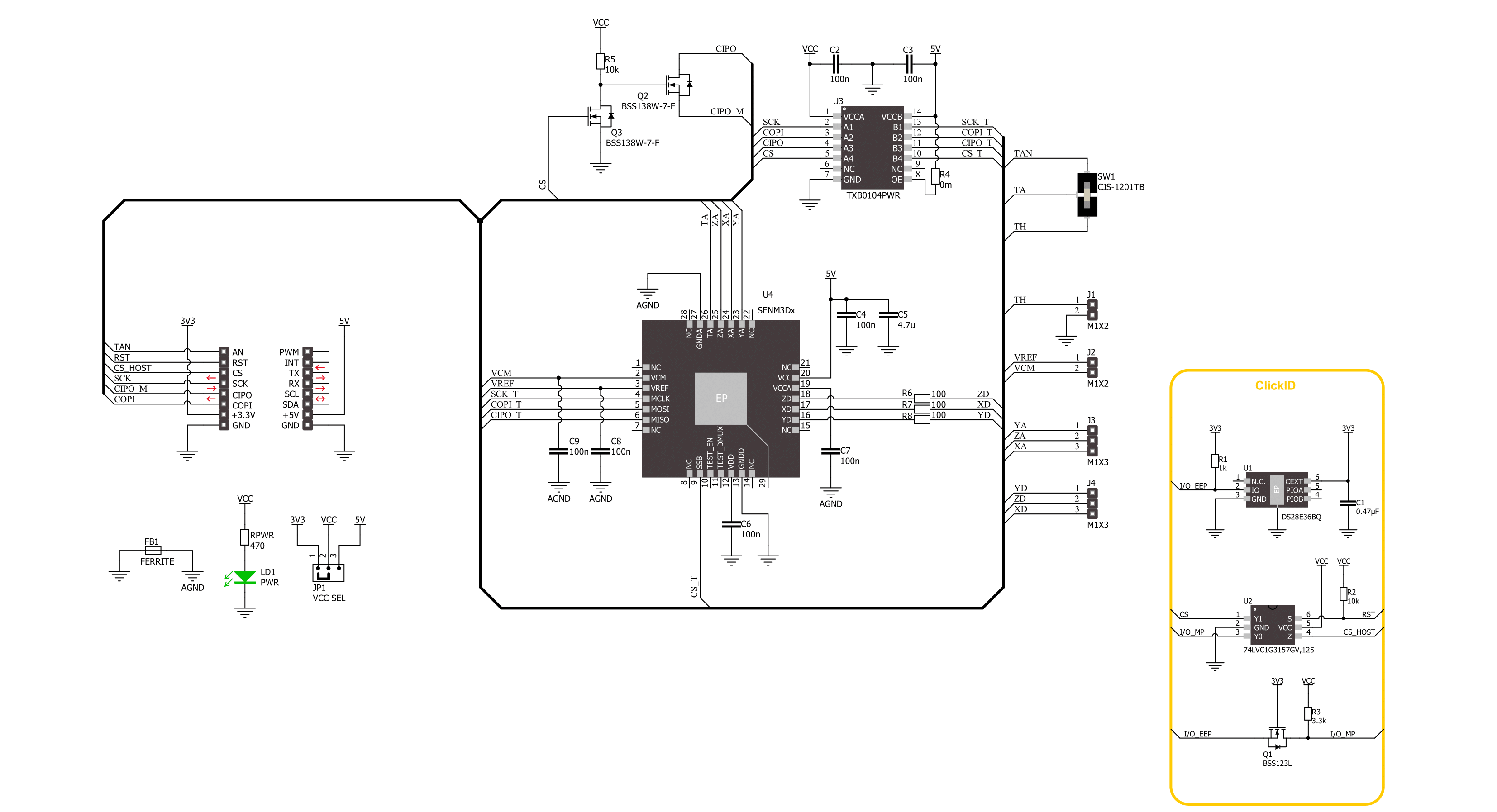
3D Hall 4 Click is based on the SENM3Dx, a 3D Hall magnetic sensor from SENIS. The sensor incorporates three groups of mutually orthogonal Hall-effect elements, of which one is horizontal and two are vertical. Each of them has biasing circuits and amplifiers. Those elements are very compact, allowing for the sensor's very high spatial resolution. In addition, by incorporating some other techniques, the sensor features high angular accuracy, significantly suppressing offset, low-frequency noise, and the planar Hall effect. The sensor provides high analog frequency bandwidth from DC to 220kHz and has a built-in temperature
sensor that measures the chip temperature. Over the TEMP OUT switch, you can select the host MCU to read the temperature or connect the sensor temperature output to the TEMP connector for testing. There are also two 3-pin headers for analog and digital output of all three magnetic field dimensions. Finally, there is VCM, a virtual ground, and VREF, a bandgap reference voltage pin. 3D Hall Click uses an SPI serial interface to communicate with the host MCU and is compatible with SPI mode 1. The sensor is a 5V device, and to allow 3.3V MCUs to work with the sensor, the 3D Hall Click is equipped with the TXB0104, a 4-bit
bidirectional voltage-level translator from Texas Instruments. The temperature output of the sensor, host MCU, can read over the AN pin if selected over the TEMP OUT switch. This Click board™ can operate with either 3.3V or 5V logic voltage levels selected via the VCC SEL jumper. This way, both 3.3V and 5V capable MCUs can use the communication lines properly. Also, this Click board™ comes equipped with a library containing easy-to-use functions and an example code that can be used as a reference for further development.

Features overview
Development board
Nucleo-64 with STM32F091RC MCU offers a cost-effective and adaptable platform for developers to explore new ideas and prototype their designs. This board harnesses the versatility of the STM32 microcontroller, enabling users to select the optimal balance of performance and power consumption for their projects. It accommodates the STM32 microcontroller in the LQFP64 package and includes essential components such as a user LED, which doubles as an ARDUINO® signal, alongside user and reset push-buttons, and a 32.768kHz crystal oscillator for precise timing operations. Designed with expansion and flexibility in mind, the Nucleo-64 board features an ARDUINO® Uno V3 expansion connector and ST morpho extension pin
headers, granting complete access to the STM32's I/Os for comprehensive project integration. Power supply options are adaptable, supporting ST-LINK USB VBUS or external power sources, ensuring adaptability in various development environments. The board also has an on-board ST-LINK debugger/programmer with USB re-enumeration capability, simplifying the programming and debugging process. Moreover, the board is designed to simplify advanced development with its external SMPS for efficient Vcore logic supply, support for USB Device full speed or USB SNK/UFP full speed, and built-in cryptographic features, enhancing both the power efficiency and security of projects. Additional connectivity is
provided through dedicated connectors for external SMPS experimentation, a USB connector for the ST-LINK, and a MIPI® debug connector, expanding the possibilities for hardware interfacing and experimentation. Developers will find extensive support through comprehensive free software libraries and examples, courtesy of the STM32Cube MCU Package. This, combined with compatibility with a wide array of Integrated Development Environments (IDEs), including IAR Embedded Workbench®, MDK-ARM, and STM32CubeIDE, ensures a smooth and efficient development experience, allowing users to fully leverage the capabilities of the Nucleo-64 board in their projects.

Microcontroller Overview
MCU Card / MCU

Architecture
ARM Cortex-M0
MCU Memory (KB)
256
Silicon Vendor
STMicroelectronics
Pin count
64
RAM (Bytes)
32768
You complete me!
Accessories
Click Shield for Nucleo-64 comes equipped with two proprietary mikroBUS™ sockets, allowing all the Click board™ devices to be interfaced with the STM32 Nucleo-64 board with no effort. This way, Mikroe allows its users to add any functionality from our ever-growing range of Click boards™, such as WiFi, GSM, GPS, Bluetooth, ZigBee, environmental sensors, LEDs, speech recognition, motor control, movement sensors, and many more. More than 1537 Click boards™, which can be stacked and integrated, are at your disposal. The STM32 Nucleo-64 boards are based on the microcontrollers in 64-pin packages, a 32-bit MCU with an ARM Cortex M4 processor operating at 84MHz, 512Kb Flash, and 96KB SRAM, divided into two regions where the top section represents the ST-Link/V2 debugger and programmer while the bottom section of the board is an actual development board. These boards are controlled and powered conveniently through a USB connection to program and efficiently debug the Nucleo-64 board out of the box, with an additional USB cable connected to the USB mini port on the board. Most of the STM32 microcontroller pins are brought to the IO pins on the left and right edge of the board, which are then connected to two existing mikroBUS™ sockets. This Click Shield also has several switches that perform functions such as selecting the logic levels of analog signals on mikroBUS™ sockets and selecting logic voltage levels of the mikroBUS™ sockets themselves. Besides, the user is offered the possibility of using any Click board™ with the help of existing bidirectional level-shifting voltage translators, regardless of whether the Click board™ operates at a 3.3V or 5V logic voltage level. Once you connect the STM32 Nucleo-64 board with our Click Shield for Nucleo-64, you can access hundreds of Click boards™, working with 3.3V or 5V logic voltage levels.

Used MCU Pins
mikroBUS™ mapper
Take a closer look
Click board™ Schematic
Step by step
Project assembly
Start by selecting your development board and Click board™. Begin with the Nucleo-64 with STM32F091RC MCU as your development board.


Software Support
Library Description
This library contains API for 3D Hall 4 Click driver.
Key functions:
c3dhall4_read_data- This function reads the measurement status, 3-axes magnetic field data, and the chip internal temperature.c3dhall4_reg_write- This function writes a desired number of data bytes starting from the selected register by using SPI serial interface.c3dhall4_reg_read- This function reads a desired number of data bytes starting from the selected register by using SPI serial interface.
Open Source
Code example
The complete application code and a ready-to-use project are available through the NECTO Studio Package Manager for direct installation in the NECTO Studio. The application code can also be found on the MIKROE GitHub account.
/*!
 * @file main.c
 * @brief 3D Hall 4 Click example
 *
 * # Description
 * This example demonstrates the use of 3D Hall 4 Click board by reading
 * the magnetic field strength from 3 axes and the sensor internal temperature.
 *
 * The demo application is composed of two sections :
 *
 * ## Application Init
 * Initializes the driver and performs the Click default configuration.
 *
 * ## Application Task
 * Reads data from the sensor and displays them on the USB UART once per second.
 *
 * @author Stefan Filipovic
 *
 */

#include "board.h"
#include "log.h"
#include "c3dhall4.h"

static c3dhall4_t c3dhall4;
static log_t logger;

void application_init ( void )
{
    log_cfg_t log_cfg;  /**< Logger config object. */
    c3dhall4_cfg_t c3dhall4_cfg;  /**< Click config object. */

    /**
     * Logger initialization.
     * Default baud rate: 115200
     * Default log level: LOG_LEVEL_DEBUG
     * @note If USB_UART_RX and USB_UART_TX
     * are defined as HAL_PIN_NC, you will
     * need to define them manually for log to work.
     * See @b LOG_MAP_USB_UART macro definition for detailed explanation.
     */
    LOG_MAP_USB_UART( log_cfg );
    log_init( &logger, &log_cfg );
    log_info( &logger, " Application Init " );

    // Click initialization.
    c3dhall4_cfg_setup( &c3dhall4_cfg );
    C3DHALL4_MAP_MIKROBUS( c3dhall4_cfg, MIKROBUS_1 );
    if ( C3DHALL4_OK != c3dhall4_init( &c3dhall4, &c3dhall4_cfg ) )
    {
        log_error( &logger, " Communication init." );
        for ( ; ; );
    }

    if ( C3DHALL4_OK != c3dhall4_default_cfg ( &c3dhall4 ) )
    {
        log_error( &logger, " Default configuration." );
        for ( ; ; );
    }

    log_info( &logger, " Application Task " );
}

void application_task ( void )
{
    c3dhall4_data_t data_res;
    if ( C3DHALL4_OK == c3dhall4_read_data ( &c3dhall4, &data_res ) )
    {
        log_printf( &logger, " Status: 0x%.2X\r\n", ( uint16_t ) data_res.status );
        log_printf( &logger, " X data: %.1f mT\r\n", data_res.x_data );
        log_printf( &logger, " Y data: %.1f mT\r\n", data_res.y_data );
        log_printf( &logger, " Z data: %.1f mT\r\n", data_res.z_data );
        log_printf( &logger, " Chip temperature: %.2f degC\r\n\n", data_res.chip_temp );
        Delay_ms ( 1000 );
    }
}

int main ( void )
{
    /* Do not remove this line or clock might not be set correctly. */
    #ifdef PREINIT_SUPPORTED
    preinit();
    #endif

    application_init( );

    for ( ; ; )
    {
        application_task( );
    }

    return 0;
}

// ------------------------------------------------------------------------ END
Additional Support
Resources
Category:Magnetic


