Enhance energy efficiency and comfort through precise lighting control based on VEML7700 and STM32F091RC
Sensing the light: A new dawn in ambient light technology

Published Feb 26, 2024
Click board™
Ambient 6 Click
Dev. board
Nucleo-64 with STM32F091RC MCU
Compiler
NECTO Studio
MCU
STM32F091RC
Experience the future of smart living with our ambient light sensors, providing intelligent, automated lighting control that seamlessly integrates with your lifestyle
A
A
Hardware Overview
How does it work?
Ambient 6 Click is based on the VEML7700, a high accuracy ambient light sensor (ALS) with I2C interface, from Vishay Semiconductors. This sensor utilizes several proprietary technologies to ensure accurate measurements of the light intensity, with the spectral response very close to a human eye. By utilizing a sensitive photo-diode, low noise amplifier, and a 16-bit A/D converter (ADC), this sensor can provide the data directly, with no need for complex calculations. The dynamic range for the ambient light sensor is very large, starting down from 0 lx up to about 167 klx, with the maximum resolution of only 0.005 lx/count. A high dynamic range along with a linear response to different light sources, allows this sensor to be placed behind a dark glass or panels made of other semi-transparent materials. The VEML7700 sensor uses only six 16-bit registers, which makes it very simple to configure and use. Even though, it comes with the mikroSDK compatible library, which simplifies the development even more. However, more detailed explanation of each command can be found in the datasheet of the
VEML7700, if required. By using these six registers, the user can configure the Click board™ and the equipped VEML7700 sensor, fine-tuning it according to the requirements of the application. All the working parameters including the sensitivity, integration time, interrupt detection, persistence protection for the interrupt triggering, low and high threshold window for the interrupt, can all be set using these registers. Finally, the Ambient Light Sensing (ALS) result can be found here in 16-bit register 0x04. The data can be read or written in LSB/MSB format, using the 8-bit I2C interface. A selectable sensitivity allows a very wide dynamic range for the ALS measurement. There are two ALS_SM bits, allowing the sensitivity to be set to 1/4, 1/8, 2, and 1 x ALS nominal sensitivity. This offers four different luminosity ranges to be covered for each selected integration time (ALS_IT). For example: the fastest integration time (25ms) results in the lowest resolution, and combined with the sensitivity of 1/8 x ALS, it allows the highest luminosity value to be measured. The event detection engine allows optimized firmware
to be developed. Although there is no dedicated interrupt pin on the VEML7700 IC, the software can still poll the status by reading two event flag bits. When any of the programmed light thresholds is exceeded for a programmed number of times (persistence protection), an interrupt event will be generated, asserting this pin to a LOW logic level. The interrupt pin is routed to the mikroBUS™ INT pin. The Click board™ is supported by the mikroSDK library, which contains functions for simplified development. The mikroSDK functions are well-documented, but there is still a need, the datasheet of the VEML7700 offers listing of all the registers and their specific functions. This Click board™ can be operated only with a 3.3V logic voltage level. The board must perform appropriate logic voltage level conversion before using MCUs with different logic levels. Also, it comes equipped with a library containing functions and an example code that can be used as a reference for further development.


Features overview
Development board
Nucleo-64 with STM32F091RC MCU offers a cost-effective and adaptable platform for developers to explore new ideas and prototype their designs. This board harnesses the versatility of the STM32 microcontroller, enabling users to select the optimal balance of performance and power consumption for their projects. It accommodates the STM32 microcontroller in the LQFP64 package and includes essential components such as a user LED, which doubles as an ARDUINO® signal, alongside user and reset push-buttons, and a 32.768kHz crystal oscillator for precise timing operations. Designed with expansion and flexibility in mind, the Nucleo-64 board features an ARDUINO® Uno V3 expansion connector and ST morpho extension pin
headers, granting complete access to the STM32's I/Os for comprehensive project integration. Power supply options are adaptable, supporting ST-LINK USB VBUS or external power sources, ensuring adaptability in various development environments. The board also has an on-board ST-LINK debugger/programmer with USB re-enumeration capability, simplifying the programming and debugging process. Moreover, the board is designed to simplify advanced development with its external SMPS for efficient Vcore logic supply, support for USB Device full speed or USB SNK/UFP full speed, and built-in cryptographic features, enhancing both the power efficiency and security of projects. Additional connectivity is
provided through dedicated connectors for external SMPS experimentation, a USB connector for the ST-LINK, and a MIPI® debug connector, expanding the possibilities for hardware interfacing and experimentation. Developers will find extensive support through comprehensive free software libraries and examples, courtesy of the STM32Cube MCU Package. This, combined with compatibility with a wide array of Integrated Development Environments (IDEs), including IAR Embedded Workbench®, MDK-ARM, and STM32CubeIDE, ensures a smooth and efficient development experience, allowing users to fully leverage the capabilities of the Nucleo-64 board in their projects.

Microcontroller Overview
MCU Card / MCU

Architecture
ARM Cortex-M0
MCU Memory (KB)
256
Silicon Vendor
STMicroelectronics
Pin count
64
RAM (Bytes)
32768
You complete me!
Accessories
Click Shield for Nucleo-64 comes equipped with two proprietary mikroBUS™ sockets, allowing all the Click board™ devices to be interfaced with the STM32 Nucleo-64 board with no effort. This way, Mikroe allows its users to add any functionality from our ever-growing range of Click boards™, such as WiFi, GSM, GPS, Bluetooth, ZigBee, environmental sensors, LEDs, speech recognition, motor control, movement sensors, and many more. More than 1537 Click boards™, which can be stacked and integrated, are at your disposal. The STM32 Nucleo-64 boards are based on the microcontrollers in 64-pin packages, a 32-bit MCU with an ARM Cortex M4 processor operating at 84MHz, 512Kb Flash, and 96KB SRAM, divided into two regions where the top section represents the ST-Link/V2 debugger and programmer while the bottom section of the board is an actual development board. These boards are controlled and powered conveniently through a USB connection to program and efficiently debug the Nucleo-64 board out of the box, with an additional USB cable connected to the USB mini port on the board. Most of the STM32 microcontroller pins are brought to the IO pins on the left and right edge of the board, which are then connected to two existing mikroBUS™ sockets. This Click Shield also has several switches that perform functions such as selecting the logic levels of analog signals on mikroBUS™ sockets and selecting logic voltage levels of the mikroBUS™ sockets themselves. Besides, the user is offered the possibility of using any Click board™ with the help of existing bidirectional level-shifting voltage translators, regardless of whether the Click board™ operates at a 3.3V or 5V logic voltage level. Once you connect the STM32 Nucleo-64 board with our Click Shield for Nucleo-64, you can access hundreds of Click boards™, working with 3.3V or 5V logic voltage levels.

Used MCU Pins
mikroBUS™ mapper
Take a closer look
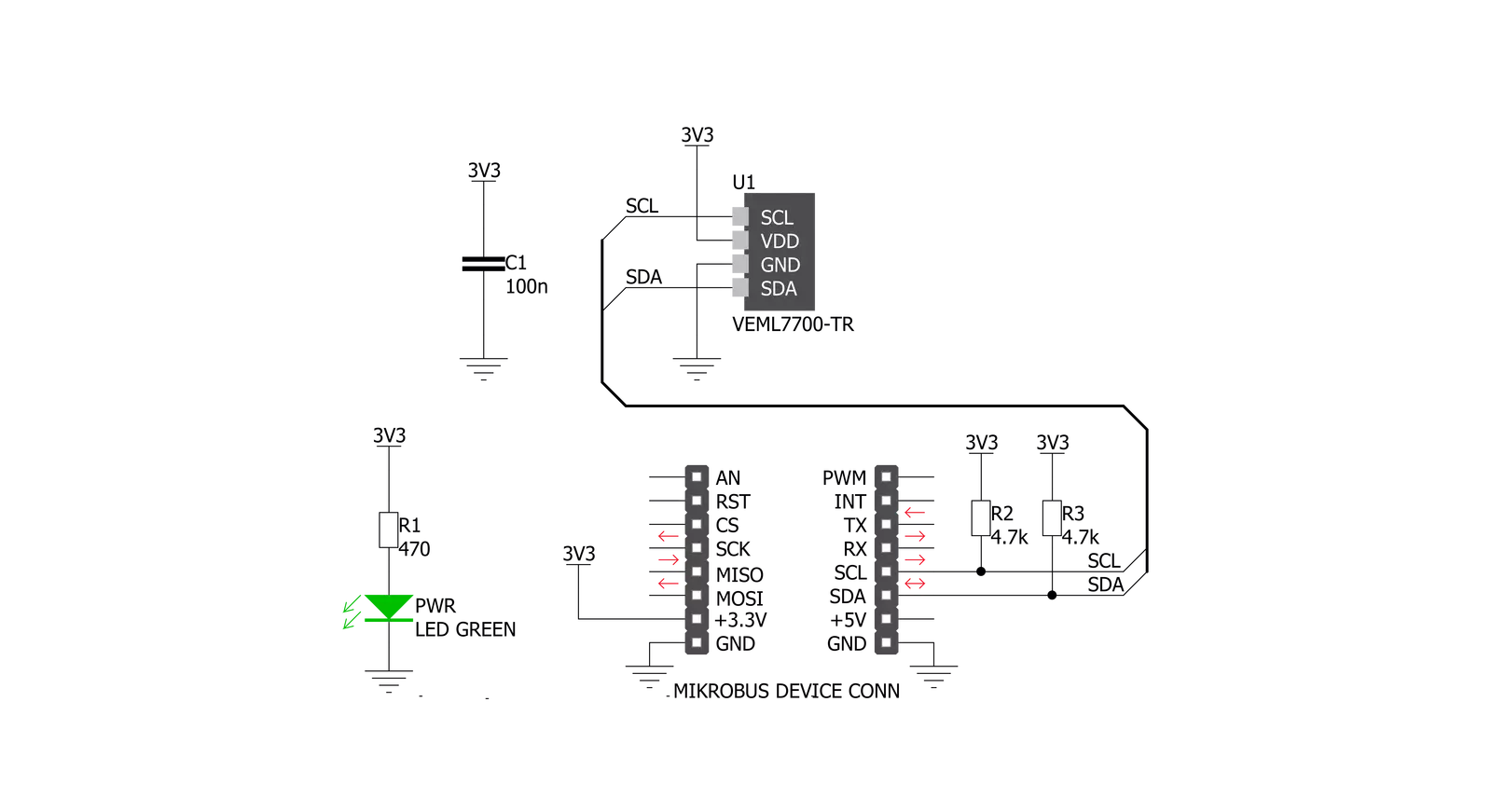
Click board™ Schematic
Step by step
Project assembly
Start by selecting your development board and Click board™. Begin with the Nucleo-64 with STM32F091RC MCU as your development board.


Track your results in real time
Application Output
1. Application Output - In Debug mode, the 'Application Output' window enables real-time data monitoring, offering direct insight into execution results. Ensure proper data display by configuring the environment correctly using the provided tutorial.

2. UART Terminal - Use the UART Terminal to monitor data transmission via a USB to UART converter, allowing direct communication between the Click board™ and your development system. Configure the baud rate and other serial settings according to your project's requirements to ensure proper functionality. For step-by-step setup instructions, refer to the provided tutorial.

3. Plot Output - The Plot feature offers a powerful way to visualize real-time sensor data, enabling trend analysis, debugging, and comparison of multiple data points. To set it up correctly, follow the provided tutorial, which includes a step-by-step example of using the Plot feature to display Click board™ readings. To use the Plot feature in your code, use the function: plot(*insert_graph_name*, variable_name);. This is a general format, and it is up to the user to replace 'insert_graph_name' with the actual graph name and 'variable_name' with the parameter to be displayed.

Software Support
Library Description
This library contains API for Ambient 6 Click driver.
Key functions:
ambient6_get_ambient_data- Functions for read 16bit Ambient Data (ALS)ambient6_configuration- Functions for configuration device for measurementambient6_get_ambient_light- Functions for get Ambient Light Data
Open Source
Code example
The complete application code and a ready-to-use project are available through the NECTO Studio Package Manager for direct installation in the NECTO Studio. The application code can also be found on the MIKROE GitHub account.
/*!
 * \file
 * \brief Ambient6 Click example
 *
 * # Description
 * This application measurement ambient light
 *
 * The demo application is composed of two sections :
 *
 * ## Application Init
 * Initialization driver init and default configuration device for measurement
 *
 * ## Application Task
 * Read Ambient Light in lux[lx] and this data logs to USBUART every 1sec.
 *
 *
 * \author MikroE Team
 *
 */
// ------------------------------------------------------------------- INCLUDES

#include "board.h"
#include "log.h"
#include "ambient6.h"

// ------------------------------------------------------------------ VARIABLES

static ambient6_t ambient6;
static log_t logger;

// ------------------------------------------------------ APPLICATION FUNCTIONS

void application_init ( void )
{
    log_cfg_t log_cfg;
    ambient6_cfg_t cfg;

    /**
     * Logger initialization.
     * Default baud rate: 115200
     * Default log level: LOG_LEVEL_DEBUG
     * @note If USB_UART_RX and USB_UART_TX
     * are defined as HAL_PIN_NC, you will
     * need to define them manually for log to work.
     * See @b LOG_MAP_USB_UART macro definition for detailed explanation.
     */
    LOG_MAP_USB_UART( log_cfg );
    log_init( &logger, &log_cfg );
    log_info( &logger, "---- Application Init ----" );

    //  Click initialization.

    ambient6_cfg_setup( &cfg );
    AMBIENT6_MAP_MIKROBUS( cfg, MIKROBUS_1 );
    ambient6_init( &ambient6, &cfg );
    ambient6_default_cfg( &ambient6 );
}

void application_task ( )
{
    float ambient_light;

    ambient_light = ambient6_get_ambient_light( &ambient6 );
    log_printf( &logger, "Ambient Light: %.2f lx \r\n", ambient_light );
    Delay_ms ( 1000 );
}

int main ( void )
{
    /* Do not remove this line or clock might not be set correctly. */
    #ifdef PREINIT_SUPPORTED
    preinit();
    #endif

    application_init( );

    for ( ; ; )
    {
        application_task( );
    }

    return 0;
}


// ------------------------------------------------------------------------ END
Additional Support
Resources
Category:Optical


