Experience the future of touch interaction with IQS227D and STM32F446RE
Advanced touch recognition

Published Oct 08, 2024
Click board™
Cap Touch 6 Click
Dev. board
Nucleo 64 with STM32F446RE MCU
Compiler
NECTO Studio
MCU
STM32F446RE
Ready to engineer the next generation of touch-sensitive applications? Explore the possibilities of our advanced capacitive touch sensing
A
A
Hardware Overview
How does it work?
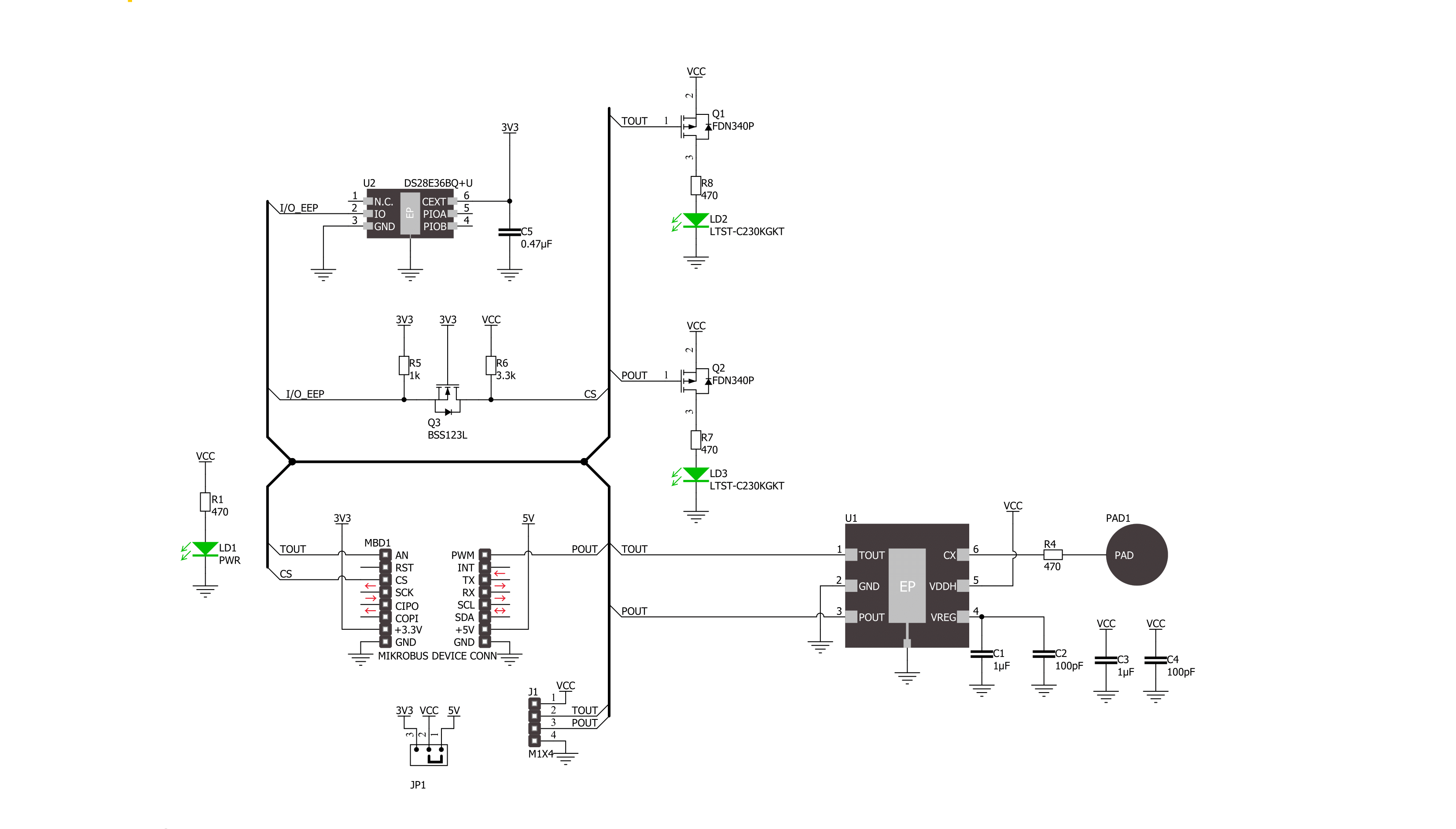
Cap Touch 6 Click is based on the IQS227D, a fully integrated single-channel capacitive controller with an internal voltage regular and reference capacitor from Azoteq. As known, the capacitive touch technology works by detecting changes in capacitance on the screen or touchpad, in this case, the sensing area at the top of the frontal side of the board, when a finger or other conductive object comes into contact with it. The IQS227D is built on ProxSense® low voltage platform, ideal for battery application, and comes with dual outputs (touch and proximity outputs don't need to be configured), a low-power mode while sensing
proximity, and an advanced on-chip digital signal processing. Touch and proximity features, alongside its mikroBUS™ pins, marked TOU and POU, only used to communicate with MCU, also have their corresponding LED indicators, labeled Touch and Proximity, reporting the activity of these features. If a touch/proximity event is detected on the onboard sensing pad, the state of the corresponding LED will be changed, indicating an activated channel. In addition to pins of the mikroBUS™ socket, these functions can also be found on the unpopulated header for external uses if they are necessary for the user in some
specific application. As mentioned earlier, this board contains a capacitive sensing area that is the only element on the top side of the board, allowing the protective acrylic plexiglass layer placement. This Click board™ can operate with either 3.3V or 5V logic voltage levels selected via the VCC SEL jumper. This way, both 3.3V and 5V capable MCUs can use the communication lines properly. Also, this Click board™ comes equipped with a library containing easy-to-use functions and an example code that can be used, as a reference, for further development.


Features overview
Development board
Nucleo-64 with STM32F446RE MCU offers a cost-effective and adaptable platform for developers to explore new ideas and prototype their designs. This board harnesses the versatility of the STM32 microcontroller, enabling users to select the optimal balance of performance and power consumption for their projects. It accommodates the STM32 microcontroller in the LQFP64 package and includes essential components such as a user LED, which doubles as an ARDUINO® signal, alongside user and reset push-buttons, and a 32.768kHz crystal oscillator for precise timing operations. Designed with expansion and flexibility in mind, the Nucleo-64 board features an ARDUINO® Uno V3 expansion connector and ST morpho extension pin
headers, granting complete access to the STM32's I/Os for comprehensive project integration. Power supply options are adaptable, supporting ST-LINK USB VBUS or external power sources, ensuring adaptability in various development environments. The board also has an on-board ST-LINK debugger/programmer with USB re-enumeration capability, simplifying the programming and debugging process. Moreover, the board is designed to simplify advanced development with its external SMPS for efficient Vcore logic supply, support for USB Device full speed or USB SNK/UFP full speed, and built-in cryptographic features, enhancing both the power efficiency and security of projects. Additional connectivity is
provided through dedicated connectors for external SMPS experimentation, a USB connector for the ST-LINK, and a MIPI® debug connector, expanding the possibilities for hardware interfacing and experimentation. Developers will find extensive support through comprehensive free software libraries and examples, courtesy of the STM32Cube MCU Package. This, combined with compatibility with a wide array of Integrated Development Environments (IDEs), including IAR Embedded Workbench®, MDK-ARM, and STM32CubeIDE, ensures a smooth and efficient development experience, allowing users to fully leverage the capabilities of the Nucleo-64 board in their projects.

Microcontroller Overview
MCU Card / MCU

Architecture
ARM Cortex-M4
MCU Memory (KB)
512
Silicon Vendor
STMicroelectronics
Pin count
64
RAM (Bytes)
131072
You complete me!
Accessories
Click Shield for Nucleo-64 comes equipped with two proprietary mikroBUS™ sockets, allowing all the Click board™ devices to be interfaced with the STM32 Nucleo-64 board with no effort. This way, Mikroe allows its users to add any functionality from our ever-growing range of Click boards™, such as WiFi, GSM, GPS, Bluetooth, ZigBee, environmental sensors, LEDs, speech recognition, motor control, movement sensors, and many more. More than 1537 Click boards™, which can be stacked and integrated, are at your disposal. The STM32 Nucleo-64 boards are based on the microcontrollers in 64-pin packages, a 32-bit MCU with an ARM Cortex M4 processor operating at 84MHz, 512Kb Flash, and 96KB SRAM, divided into two regions where the top section represents the ST-Link/V2 debugger and programmer while the bottom section of the board is an actual development board. These boards are controlled and powered conveniently through a USB connection to program and efficiently debug the Nucleo-64 board out of the box, with an additional USB cable connected to the USB mini port on the board. Most of the STM32 microcontroller pins are brought to the IO pins on the left and right edge of the board, which are then connected to two existing mikroBUS™ sockets. This Click Shield also has several switches that perform functions such as selecting the logic levels of analog signals on mikroBUS™ sockets and selecting logic voltage levels of the mikroBUS™ sockets themselves. Besides, the user is offered the possibility of using any Click board™ with the help of existing bidirectional level-shifting voltage translators, regardless of whether the Click board™ operates at a 3.3V or 5V logic voltage level. Once you connect the STM32 Nucleo-64 board with our Click Shield for Nucleo-64, you can access hundreds of Click boards™, working with 3.3V or 5V logic voltage levels.

Used MCU Pins
mikroBUS™ mapper
Take a closer look
Click board™ Schematic
Step by step
Project assembly
Start by selecting your development board and Click board™. Begin with the Nucleo 64 with STM32F446RE MCU as your development board.


Software Support
Library Description
This library contains API for Cap Touch 6 Click driver.
Key functions:
captouch6_get_tout_pin- This function returns the TOUT pin logic statecaptouch6_get_pout_pin- This function returns the POUT pin logic state
Open Source
Code example
The complete application code and a ready-to-use project are available through the NECTO Studio Package Manager for direct installation in the NECTO Studio. The application code can also be found on the MIKROE GitHub account.
/*!
 * @file main.c
 * @brief Cap Touch 6 Click Example.
 *
 * # Description
 * This example demonstrates the use of Cap Touch 6 Click board by reading and displaying
 * the touch and proximity events.
 *
 * The demo application is composed of two sections :
 *
 * ## Application Init
 * Initializes the driver and logger.
 *
 * ## Application Task
 * Reads the touch and proximity event pins state and displays them on the USB UART on changes.
 *
 * @author Stefan Filipovic
 *
 */

#include "board.h"
#include "log.h"
#include "captouch6.h"

static captouch6_t captouch6;   /**< Cap Touch 6 Click driver object. */
static log_t logger;    /**< Logger object. */

void application_init ( void )
{
    log_cfg_t log_cfg;  /**< Logger config object. */
    captouch6_cfg_t captouch6_cfg;  /**< Click config object. */

    /**
     * Logger initialization.
     * Default baud rate: 115200
     * Default log level: LOG_LEVEL_DEBUG
     * @note If USB_UART_RX and USB_UART_TX
     * are defined as HAL_PIN_NC, you will
     * need to define them manually for log to work.
     * See @b LOG_MAP_USB_UART macro definition for detailed explanation.
     */
    LOG_MAP_USB_UART( log_cfg );
    log_init( &logger, &log_cfg );
    log_info( &logger, " Application Init " );

    // Click initialization.
    captouch6_cfg_setup( &captouch6_cfg );
    CAPTOUCH6_MAP_MIKROBUS( captouch6_cfg, MIKROBUS_1 );
    if ( DIGITAL_OUT_UNSUPPORTED_PIN == captouch6_init( &captouch6, &captouch6_cfg ) )
    {
        log_error( &logger, " Communication init." );
        for ( ; ; );
    }
    log_info( &logger, " Application Task " );
}

void application_task ( void )
{
    static uint8_t old_touch_state = 0, old_prox_state = 0;
    uint8_t touch_state = captouch6_get_tout_pin ( &captouch6 );
    uint8_t prox_state = captouch6_get_pout_pin ( &captouch6 );
    if ( ( old_touch_state != touch_state ) || ( old_prox_state != prox_state ) )
    {
        log_printf( &logger, " Touch: %s\r\n", ( char * ) ( !touch_state ? "detected" : "idle" ) );
        log_printf( &logger, " Proximity: %s\r\n\n", ( char * ) ( !prox_state ? "detected" : "idle" ) );
        old_touch_state = touch_state;
        old_prox_state = prox_state;
    }
}

int main ( void )
{
    /* Do not remove this line or clock might not be set correctly. */
    #ifdef PREINIT_SUPPORTED
    preinit();
    #endif

    application_init( );

    for ( ; ; )
    {
        application_task( );
    }

    return 0;
}

// ------------------------------------------------------------------------ END
Additional Support
Resources
Category:Capacitive


