Simplify color management and decision-making with APDS-9151 and STM32F091RC
The future of color analysis has arrived

Published Feb 26, 2024
Click board™
Color 14 Click
Dev. board
Nucleo-64 with STM32F091RC MCU
Compiler
NECTO Studio
MCU
STM32F091RC
Elevate your perception of the world around you through precise color sensing and analysis
A
A
Hardware Overview
How does it work?
Color 14 Click is based on the APDS-9151, a digital I2C compatible interface ambient light sensor (ALS), RGB, and proximity sensor with IR LED from Broadcom Limited. It uses four channels (Red, Green, Blue, and IR) in a specially designed matrix arrangement to achieve optimal angular response and accurate RGB spectral response with high lux accuracy over various light sources. It is suitable for use under a small aperture of the devices' cover windows, providing optimum viewing in diverse lighting conditions. The proximity detection feature operates well from bright sunlight to dark rooms. Proximity resolution can vary from 8bits to 11bits, with the measurement rate from 6.25ms to 400ms. To offset unwanted reflected light from the cover glass, a proximity detection (PS) intelligent cancellation level register allows an on-chip subtraction of the ADC count caused by the
unwanted reflected light from PS ADC output. Both the PS and ALS function independently provides maximum flexibility in application. The APDS-9151 has a wide dynamic range, with a programmable current in eight different steps and the LED modulation frequency, which can be set from 60kHz to 100kHz in five steps. Adding the micro-optic lenses within the module provides highly efficient transmission and reception of infrared energy, which lowers overall power dissipation. In addition, the device can be put into a low-power Standby mode, providing low average power consumption. Color 14 Click communicates with MCU using the standard I2C 2-Wire interface with a frequency of 100kHz in Standard and up to 400kHz in Fast Mode. Since the sensor is supplied with only a 3.3V logic voltage level, the Color 14 Click also features PCA9306 and SN74LVC1T45
voltage-level translators, allowing this Click board™ to be interfaced with both 3.3V and 5V MCUs. It also generates flexible ambient and proximity programmable interrupt signals routed on the INT pin of the mikroBUS™ socket, which is triggered if upper or lower threshold values are crossed. It is also possible to deactivate both sensors after a specific interrupt event occurs. This Click board™ can operate with either 3.3V or 5V logic voltage levels selected via the VIO SEL jumper. This way, both 3.3V and 5V capable MCUs can use the communication lines properly. Also, this Click board™ comes equipped with a library containing easy-to-use functions and an example code that can be used as a reference for further development.


Features overview
Development board
Nucleo-64 with STM32F091RC MCU offers a cost-effective and adaptable platform for developers to explore new ideas and prototype their designs. This board harnesses the versatility of the STM32 microcontroller, enabling users to select the optimal balance of performance and power consumption for their projects. It accommodates the STM32 microcontroller in the LQFP64 package and includes essential components such as a user LED, which doubles as an ARDUINO® signal, alongside user and reset push-buttons, and a 32.768kHz crystal oscillator for precise timing operations. Designed with expansion and flexibility in mind, the Nucleo-64 board features an ARDUINO® Uno V3 expansion connector and ST morpho extension pin
headers, granting complete access to the STM32's I/Os for comprehensive project integration. Power supply options are adaptable, supporting ST-LINK USB VBUS or external power sources, ensuring adaptability in various development environments. The board also has an on-board ST-LINK debugger/programmer with USB re-enumeration capability, simplifying the programming and debugging process. Moreover, the board is designed to simplify advanced development with its external SMPS for efficient Vcore logic supply, support for USB Device full speed or USB SNK/UFP full speed, and built-in cryptographic features, enhancing both the power efficiency and security of projects. Additional connectivity is
provided through dedicated connectors for external SMPS experimentation, a USB connector for the ST-LINK, and a MIPI® debug connector, expanding the possibilities for hardware interfacing and experimentation. Developers will find extensive support through comprehensive free software libraries and examples, courtesy of the STM32Cube MCU Package. This, combined with compatibility with a wide array of Integrated Development Environments (IDEs), including IAR Embedded Workbench®, MDK-ARM, and STM32CubeIDE, ensures a smooth and efficient development experience, allowing users to fully leverage the capabilities of the Nucleo-64 board in their projects.

Microcontroller Overview
MCU Card / MCU

Architecture
ARM Cortex-M0
MCU Memory (KB)
256
Silicon Vendor
STMicroelectronics
Pin count
64
RAM (Bytes)
32768
You complete me!
Accessories
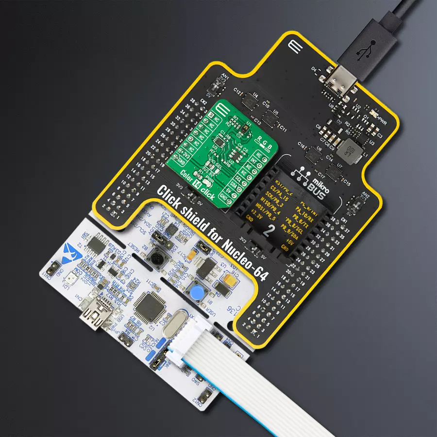
Click Shield for Nucleo-64 comes equipped with two proprietary mikroBUS™ sockets, allowing all the Click board™ devices to be interfaced with the STM32 Nucleo-64 board with no effort. This way, Mikroe allows its users to add any functionality from our ever-growing range of Click boards™, such as WiFi, GSM, GPS, Bluetooth, ZigBee, environmental sensors, LEDs, speech recognition, motor control, movement sensors, and many more. More than 1537 Click boards™, which can be stacked and integrated, are at your disposal. The STM32 Nucleo-64 boards are based on the microcontrollers in 64-pin packages, a 32-bit MCU with an ARM Cortex M4 processor operating at 84MHz, 512Kb Flash, and 96KB SRAM, divided into two regions where the top section represents the ST-Link/V2 debugger and programmer while the bottom section of the board is an actual development board. These boards are controlled and powered conveniently through a USB connection to program and efficiently debug the Nucleo-64 board out of the box, with an additional USB cable connected to the USB mini port on the board. Most of the STM32 microcontroller pins are brought to the IO pins on the left and right edge of the board, which are then connected to two existing mikroBUS™ sockets. This Click Shield also has several switches that perform functions such as selecting the logic levels of analog signals on mikroBUS™ sockets and selecting logic voltage levels of the mikroBUS™ sockets themselves. Besides, the user is offered the possibility of using any Click board™ with the help of existing bidirectional level-shifting voltage translators, regardless of whether the Click board™ operates at a 3.3V or 5V logic voltage level. Once you connect the STM32 Nucleo-64 board with our Click Shield for Nucleo-64, you can access hundreds of Click boards™, working with 3.3V or 5V logic voltage levels.

Used MCU Pins
mikroBUS™ mapper
Take a closer look
Click board™ Schematic

Step by step
Project assembly
Start by selecting your development board and Click board™. Begin with the Nucleo-64 with STM32F091RC MCU as your development board.


Software Support
Library Description
This library contains API for Color 14 Click driver.
Key functions:
color14_get_rgb_ir- Read color data from devicecolor14_get_als- Read lux data from devicecolor14_get_proximity- Read proximity data from device
Open Source
Code example
The complete application code and a ready-to-use project are available through the NECTO Studio Package Manager for direct installation in the NECTO Studio. The application code can also be found on the MIKROE GitHub account.
/*!
 * @file main.c
 * @brief Color14 Click example
 *
 * # Description
 * This application showcases ability of Click board to read RGB and IR data
 * from device. Also it can be configured to read proximity data and
 * ALS data in lux units.
 *
 * The demo application is composed of two sections :
 *
 * ## Application Init
 * Initialization of host communication modules (UART, I2C) and additonal pin.
 * Read and check device ID, selects example and configures device for it.
 *
 * ## Application Task
 * Depending of selected example in task proximity and als data will be read from
 * device, or it will show ADC value for red, green, blue and ir data from device.
 *
 * ### Additioal function
 * static void color13_proximity_als_example ( void );
 * static void color13_rgb_example ( void );
 *
 * @author Luka Filipovic
 *
 */

#include "board.h"
#include "log.h"
#include "color14.h"

#define COLOR14_EXAMPLE_PS_LS   3
#define COLOR14_EXAMPLE_RGB     6

static color14_t color14;
static log_t logger;

static uint8_t example_type;

/**
 * @brief Proximity and Als data reading.
 * @details Example function for reading proximity and als data.
 * @return Nothing
 */
static void color14_proximity_als_example ( void );

/**
 * @brief RGB data reading.
 * @details Example function for reading rgb and ir data.
 * @return Nothing
 */
static void color14_rgb_example ( void );

void application_init ( void )
{
    log_cfg_t log_cfg;  /**< Logger config object. */
    color14_cfg_t color14_cfg;  /**< Click config object. */

    /**
     * Logger initialization.
     * Default baud rate: 115200
     * Default log level: LOG_LEVEL_DEBUG
     * @note If USB_UART_RX and USB_UART_TX
     * are defined as HAL_PIN_NC, you will
     * need to define them manually for log to work.
     * See @b LOG_MAP_USB_UART macro definition for detailed explanation.
     */
    LOG_MAP_USB_UART( log_cfg );
    log_init( &logger, &log_cfg );
    log_info( &logger, " Application Init " );

    // Click initialization.
    color14_cfg_setup( &color14_cfg );
    COLOR14_MAP_MIKROBUS( color14_cfg, MIKROBUS_1 );
    err_t init_flag = color14_init( &color14, &color14_cfg );
    if ( I2C_MASTER_ERROR == init_flag )
    {
        log_error( &logger, " Application Init Error. " );
        log_info( &logger, " Please, run program again... " );

        for ( ; ; );
    }

    uint8_t temp_data = 0;
    init_flag = color14_generic_read( &color14, COLOR14_REG_PART_ID, &temp_data, 1 );
    log_printf( &logger, " > ID: 0x%.2X\r\n", ( uint16_t )temp_data );

    if ( ( COLOR14_OK != init_flag ) && ( COLOR14_ID != temp_data ) )
    {
        log_error( &logger, " ID" );
        log_info( &logger, " Please, run program again... " );

        for ( ; ; );
    }

    //Select example
    example_type = COLOR14_EXAMPLE_RGB;
    color14_generic_write( &color14, COLOR14_REG_MAIN_CTRL, &example_type, 1 );

    if ( COLOR14_EXAMPLE_PS_LS == example_type )
    {
        //Configure proximity data to 11 bit
        color14_generic_read( &color14, COLOR14_REG_PS_MEASRATE, &temp_data, 1 );
        temp_data |= 0x18;
        color14_generic_write( &color14, COLOR14_REG_PS_MEASRATE, &temp_data, 1 );
    }

    Delay_ms ( 1000 );
    log_info( &logger, " Application Task " );
}

void application_task ( void )
{
    switch ( example_type )
    {
        case COLOR14_EXAMPLE_PS_LS:
        {
            color14_proximity_als_example( );
            break;
        }
        case COLOR14_EXAMPLE_RGB:
        {
            color14_rgb_example( );
            break;
        }
        default:
        {
            log_error( &logger, " Select example!" );
            break;
        }
    }
    Delay_ms ( 500 );
}

int main ( void )
{
    /* Do not remove this line or clock might not be set correctly. */
    #ifdef PREINIT_SUPPORTED
    preinit();
    #endif

    application_init( );

    for ( ; ; )
    {
        application_task( );
    }

    return 0;
}

static void color14_proximity_als_example ( void )
{
    //Proximity data
    uint16_t ps_data = 0;
    err_t error_flag = color14_get_proximity( &color14, &ps_data );
    log_printf( &logger, " > PS: %u\r\n", ps_data );
    if ( COLOR14_ERROR_OVF == error_flag )
    {
        log_error( &logger, " Overflow" );
    }
    //ALS data
    float lux = 0;
    color14_get_als( &color14, &lux );
    log_printf( &logger, " > LS[ lux ]: %.2f\r\n", lux );
    log_printf( &logger, "**********************************\r\n" );
}

static void color14_rgb_example ( void )
{
    color14_color_t color_data;

    color14_get_rgb_ir( &color14, &color_data );

    log_printf( &logger, " > R: %u\r\n", color_data.red );
    log_printf( &logger, " > G: %u\r\n", color_data.green );
    log_printf( &logger, " > B: %u\r\n", color_data.blue );
    log_printf( &logger, " > IR: %u\r\n", color_data.ir );
    log_printf( &logger, "**********************************\r\n" );
}

// ------------------------------------------------------------------------ END
Additional Support
Resources
Category:Optical


