Limit currents/voltages to safe levels during fault conditions with TPS259631 and STM32F091RC
Safeguarding performance, enhancing efficiency

Published Feb 26, 2024
Click board™
eFuse 2 Click
Dev. board
Nucleo-64 with STM32F091RC MCU
Compiler
NECTO Studio
MCU
STM32F091RC
Our eFuse device is engineered to revolutionize power management, providing precision control over load voltage and load current to enhance device performance, protect against faults, and ensure reliability
A
A
Hardware Overview
How does it work?
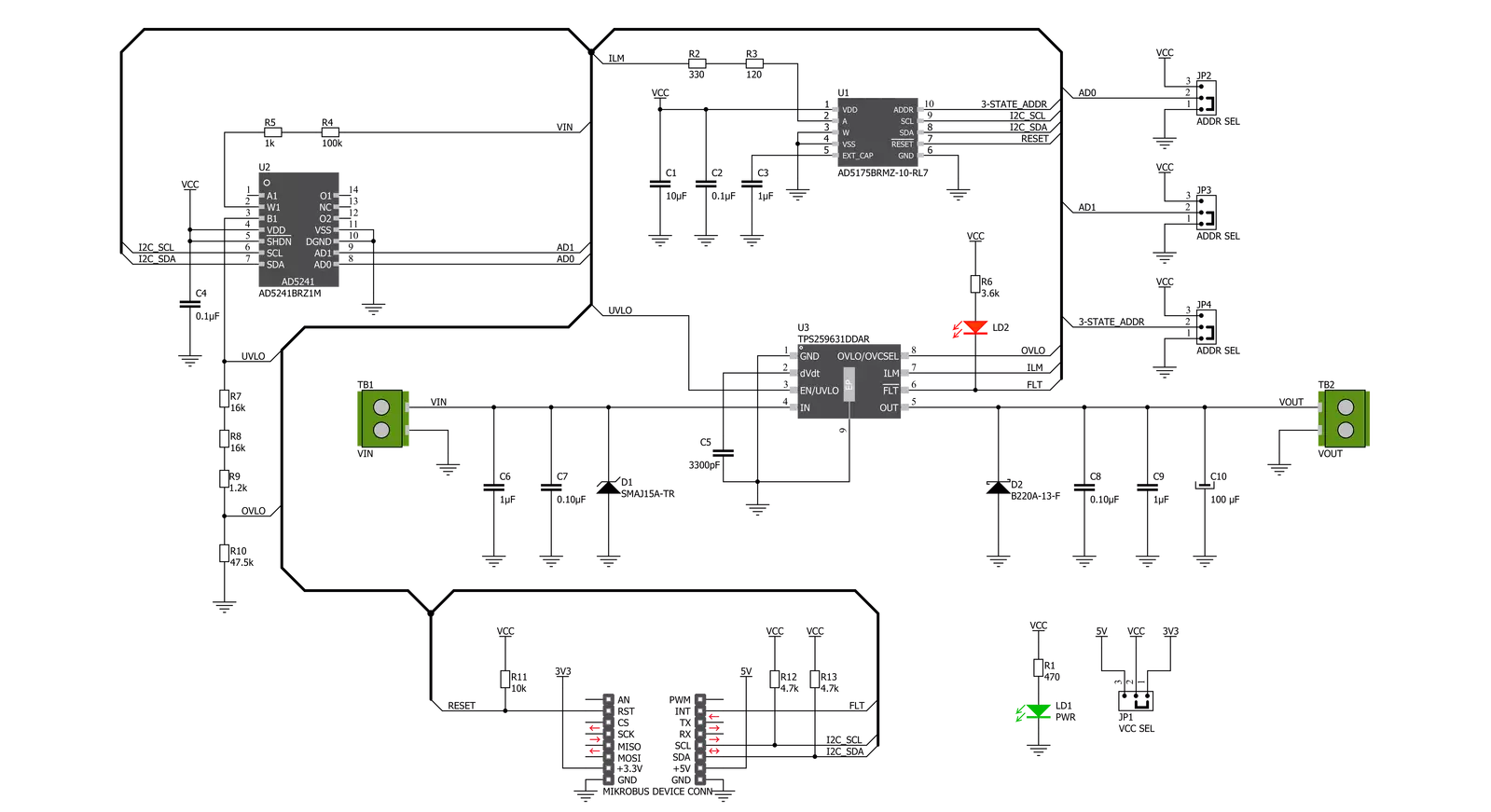
eFuse 2 Click is based on the TPS259631, an integrated eFuse device that manages load voltage and load current from Texas Instruments. The TPS259631 provides various factory-programmed settings and user-manageable settings, allowing device configuration to handle different transient and steady-state supply and load fault conditions, thereby protecting the input supply and the downstream circuits connected to the device. The device also uses an in-built thermal shutdown mechanism to shield itself during these fault events. This Click board™ provides a simple solution for current limiting, inrush current control, and supervision of power rails for a wide range of applications operating from 2.7 V to 19 V external power supply and delivering up to 2A. Besides, the eFuse 2 Click board™ monitors the input supply the entire time and comes up with a user-adjustable UVLO and
OVLO mechanism through an I2C compatible digital potentiometer, the AD5241 from Analog Devices to ensure that the load is powered up only when the voltage is at a sufficient level. It is also possible to get an accurate sense of the output load current by measuring the voltage drop across the current limit resistor. By replacing the resistor with a digital rheostat, you can easily program the current limit as performed on this Click board™. For this purpose, the AD5175 single-channel 1024-position digital rheostat from Analog Devices that communicate with the MCU through the I2C serial interface is used to program the current limit. The TPS259631 regulates the current to the set current limit value within the nominal overcurrent response time and exits current limiting when the load current falls below the current limit value. The eFuse 2 Click board™ allows the choice of the least significant bit (LSB) of the I2C addresses for
AD5241 and AD5175. This can be performed by positioning the SMD jumper labeled as ADDR SEL to its appropriate position. Additional functionality, such as hardware reset for AD5175 and fault indication interrupt, is provided and routed at RST and INT pins of the mikroBUS™ socket labeled as RST and FLT. This open-drain fault output is associated with a red LED indicator, marked as the FLT, that will be pulled low when a fault is detected. This Click board™ can operate with either 3.3V or 5V logic voltage levels selected via the VCC SEL jumper. This way, both 3.3V and 5V capable MCUs can use the communication lines properly. Also, this Click board™ comes equipped with a library containing easy-to-use functions and an example code that can be used as a reference for further development.

Features overview
Development board
Nucleo-64 with STM32F091RC MCU offers a cost-effective and adaptable platform for developers to explore new ideas and prototype their designs. This board harnesses the versatility of the STM32 microcontroller, enabling users to select the optimal balance of performance and power consumption for their projects. It accommodates the STM32 microcontroller in the LQFP64 package and includes essential components such as a user LED, which doubles as an ARDUINO® signal, alongside user and reset push-buttons, and a 32.768kHz crystal oscillator for precise timing operations. Designed with expansion and flexibility in mind, the Nucleo-64 board features an ARDUINO® Uno V3 expansion connector and ST morpho extension pin
headers, granting complete access to the STM32's I/Os for comprehensive project integration. Power supply options are adaptable, supporting ST-LINK USB VBUS or external power sources, ensuring adaptability in various development environments. The board also has an on-board ST-LINK debugger/programmer with USB re-enumeration capability, simplifying the programming and debugging process. Moreover, the board is designed to simplify advanced development with its external SMPS for efficient Vcore logic supply, support for USB Device full speed or USB SNK/UFP full speed, and built-in cryptographic features, enhancing both the power efficiency and security of projects. Additional connectivity is
provided through dedicated connectors for external SMPS experimentation, a USB connector for the ST-LINK, and a MIPI® debug connector, expanding the possibilities for hardware interfacing and experimentation. Developers will find extensive support through comprehensive free software libraries and examples, courtesy of the STM32Cube MCU Package. This, combined with compatibility with a wide array of Integrated Development Environments (IDEs), including IAR Embedded Workbench®, MDK-ARM, and STM32CubeIDE, ensures a smooth and efficient development experience, allowing users to fully leverage the capabilities of the Nucleo-64 board in their projects.

Microcontroller Overview
MCU Card / MCU

Architecture
ARM Cortex-M0
MCU Memory (KB)
256
Silicon Vendor
STMicroelectronics
Pin count
64
RAM (Bytes)
32768
You complete me!
Accessories
Click Shield for Nucleo-64 comes equipped with two proprietary mikroBUS™ sockets, allowing all the Click board™ devices to be interfaced with the STM32 Nucleo-64 board with no effort. This way, Mikroe allows its users to add any functionality from our ever-growing range of Click boards™, such as WiFi, GSM, GPS, Bluetooth, ZigBee, environmental sensors, LEDs, speech recognition, motor control, movement sensors, and many more. More than 1537 Click boards™, which can be stacked and integrated, are at your disposal. The STM32 Nucleo-64 boards are based on the microcontrollers in 64-pin packages, a 32-bit MCU with an ARM Cortex M4 processor operating at 84MHz, 512Kb Flash, and 96KB SRAM, divided into two regions where the top section represents the ST-Link/V2 debugger and programmer while the bottom section of the board is an actual development board. These boards are controlled and powered conveniently through a USB connection to program and efficiently debug the Nucleo-64 board out of the box, with an additional USB cable connected to the USB mini port on the board. Most of the STM32 microcontroller pins are brought to the IO pins on the left and right edge of the board, which are then connected to two existing mikroBUS™ sockets. This Click Shield also has several switches that perform functions such as selecting the logic levels of analog signals on mikroBUS™ sockets and selecting logic voltage levels of the mikroBUS™ sockets themselves. Besides, the user is offered the possibility of using any Click board™ with the help of existing bidirectional level-shifting voltage translators, regardless of whether the Click board™ operates at a 3.3V or 5V logic voltage level. Once you connect the STM32 Nucleo-64 board with our Click Shield for Nucleo-64, you can access hundreds of Click boards™, working with 3.3V or 5V logic voltage levels.

Used MCU Pins
mikroBUS™ mapper
Take a closer look
Click board™ Schematic
Step by step
Project assembly
Start by selecting your development board and Click board™. Begin with the Nucleo-64 with STM32F091RC MCU as your development board.


Software Support
Library Description
This library contains API for eFuse 2 Click driver.
Key functions:
efuse2_set_operating_voltage- Set operating voltage functionefuse2_set_current_limit- Set operating current functionefuse2_get_fault- Get fault function
Open Source
Code example
The complete application code and a ready-to-use project are available through the NECTO Studio Package Manager for direct installation in the NECTO Studio. The application code can also be found on the MIKROE GitHub account.
/*!
 * @file main.c
 * @brief eFuse2 Click example
 *
 * # Description
 * This is an example that demonstrate the use of the eFuse 2 Click board.
 *
 * The demo application is composed of two sections :
 *
 * ## Application Init
 * Initialization driver enables - I2C,
 * AD5175: enable write, set the normal operating mode and operating
 * current to the 1,2 A;
 * AD5241: set operating voltage to the 12,0 V;
 * display diagnostic states.
 *
 * ## Application Task
 * eFuse 2 Click board uses USB UART log to display
 * operating voltage, OVLO, UVLO and current limit condition.
 * This firmware provides the functions to set the operating voltage and
 * current limiting conditions in order to provide the threshold
 * of the fault conditions. When one of the fault conditions is met,
 * the microcontroller is notified via INT pin which is checked
 * by the app to initiate a shutdown mode.
 * All data logs write on USB UART changes every 2000 milliseconds.
 *
 * @author Stefan Ilic
 *
 */

#include "board.h"
#include "log.h"
#include "efuse2.h"

static efuse2_t efuse2;
static log_t logger;

float op_current;
float op_voltage;
float min_voltage;
float max_voltage;

void application_init ( void )
{
    log_cfg_t log_cfg;  /**< Logger config object. */
    efuse2_cfg_t efuse2_cfg;  /**< Click config object. */

    /**
     * Logger initialization.
     * Default baud rate: 115200
     * Default log level: LOG_LEVEL_DEBUG
     * @note If USB_UART_RX and USB_UART_TX
     * are defined as HAL_PIN_NC, you will
     * need to define them manually for log to work.
     * See @b LOG_MAP_USB_UART macro definition for detailed explanation.
     */
    LOG_MAP_USB_UART( log_cfg );
    log_init( &logger, &log_cfg );
    log_info( &logger, " Application Init " );

    // Click initialization.
    efuse2_cfg_setup( &efuse2_cfg );
    EFUSE2_MAP_MIKROBUS( efuse2_cfg, MIKROBUS_1 );
    err_t init_flag = efuse2_init( &efuse2, &efuse2_cfg );
    if ( I2C_MASTER_ERROR == init_flag )
    {
        log_error( &logger, " Application Init Error. " );
        log_info( &logger, " Please, run program again... " );
        for ( ; ; );
    }

    if ( EFUSE2_ERROR == efuse2_default_cfg ( &efuse2 ) )
    {
        log_error( &logger, " Default configuration." );
        for ( ; ; );
    }
    Delay_ms ( 100 );
    op_current = 1.2;
    op_voltage = 12.0;

    log_printf( &logger, "-----------------------------\r\n" );
    log_printf( &logger, "    Set operating  value:    \r\n" );
    log_printf( &logger, "       Voltage: 12.0 V       \r\n" );
    efuse2_set_operating_voltage( &efuse2, op_voltage, &min_voltage, &max_voltage );
    Delay_ms ( 1000 );

    log_printf( &logger, "       Current:  1.2 A       \r\n" );
    log_printf( &logger, "-----------------------------\r\n" );
    efuse2_set_current_limit( &efuse2, op_current );
    Delay_ms ( 1000 );

    log_printf( &logger, "    Turn ON Power Supply     \r\n" );
    log_printf( &logger, "-----------------------------\r\n" );
    log_info( &logger, " Application Task " );
}

void application_task ( void )
{
    if ( EFUSE2_FAULT == efuse2_get_fault( &efuse2 ) )
    {
        efuse2_operating_mode( &efuse2, EFUSE2_AD5175_SHUTDOWN_MODE );
        Delay_ms ( 1000 );

        log_printf( &logger, "        Shutdown Mode        \r\n" );
        log_printf( &logger, "  Turn OFF the Power Supply  \r\n" );
        log_printf( &logger, "   and restart the system    \r\n" );
        log_printf( &logger, "-----------------------------\r\n" );

        for ( ; ; );
    }
    else
    {
        log_printf( &logger, " Oper. Voltage : %.3f V \r\n", op_voltage );
        log_printf( &logger, " Undervoltage  : %.3f V \r\n", min_voltage );
        log_printf( &logger, " Overvoltage   : %.3f V \r\n", max_voltage );
        log_printf( &logger, " Current Limit : %.3f A \r\n", op_current );
        log_printf( &logger, "-----------------------------\r\n" );
    }
    Delay_ms ( 1000 );
    Delay_ms ( 1000 );
}

int main ( void )
{
    /* Do not remove this line or clock might not be set correctly. */
    #ifdef PREINIT_SUPPORTED
    preinit();
    #endif

    application_init( );

    for ( ; ; )
    {
        application_task( );
    }

    return 0;
}

// ------------------------------------------------------------------------ END
Additional Support
Resources
Category:Power Switch


