Take charge of operations and restore settings with ease using QT1011 and STM32L073RZ
Command and Safeguard

Published Feb 26, 2024
Click board™
Power/Reset Click
Dev. board
Nucleo-64 with STM32L073RZ MCU
Compiler
NECTO Studio
MCU
STM32L073RZ
Effortlessly control device states with the ON/OFF button and, when needed, utilize the RESET button to restore settings to default swiftly, ensuring efficient management and seamless operation
A
A
Hardware Overview
How does it work?
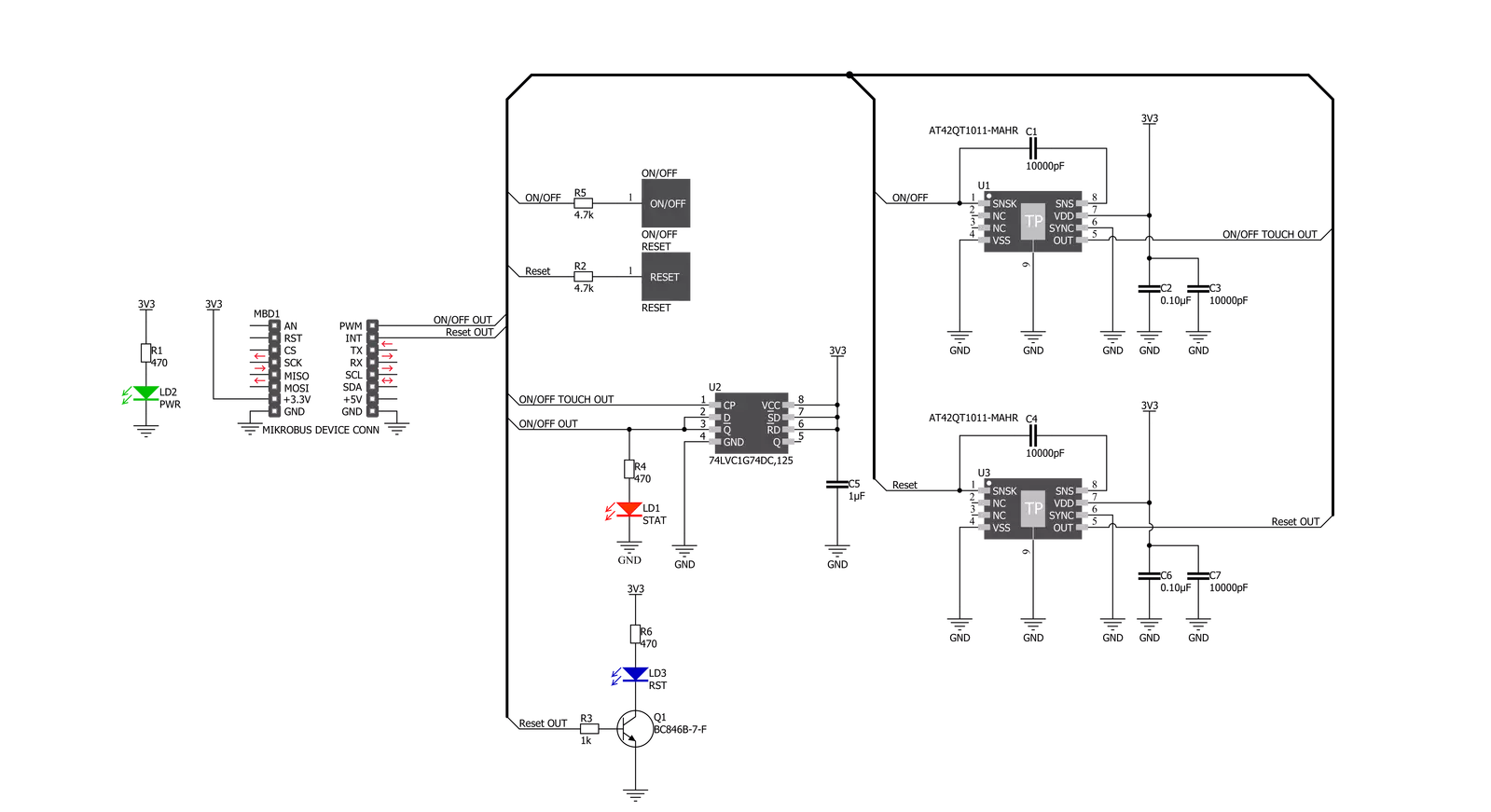
Power/Reset Click is based on the QT1011, a digital burst mode charge-transfer sensor capable of detecting proximity or touch from Microchip. This click board™ has two PCB pads to sense touch or proximity events. Besides the two touch-sensitive pads, Power/Reset click has two LEDs for the touch indication. The two touch pads use two separate QT1011 ICs, providing reliable touch-sensing functionality. The AT42QT1011 is a digital burst mode charge-transfer sensor capable of detecting proximity or touch, making it ideal for implementing touch controls. With the proper electrode and circuit design, the self-contained digital IC will project a touch or proximity field to several centimeters through any dielectric like glass, plastic, stone, ceramic, and even most kinds
of wood. It can also turn small metal-bearing objects into intrinsic sensors responsive to proximity or touch. This capability and its ability to self-calibrate can lead to entirely new product concepts. The QT1011 is designed for human interfaces like control panels, appliances, toys, lighting controls, or anywhere a mechanical switch or button may be found. It includes all hardware and signal processing functions necessary to provide stable sensing under various changing conditions. However, this click board™ is designed to serve as a power and reset capacitive switch panel board. Besides the QT1011, this click board™ contains 74LVC1G74 as well. It is a Single D-type flip-flop with set and reset. Because the output of the QT1011 is active-high upon detection, the
74LVC1G74 is triggered by the positive edge of the ON/OFF touchpad. It is wired in a cascade with the QT1011 in a way that ensures holding one logical state until the ON/OFF pad is pressed. Therefore, the ON/OFF pad acts like a switch, while the RESET pad acts like a button, which is suitable for most common purposes. The ON/OFF and RESET pad output signals are wired to the PWM and INT pins on the mikroBUS™, respectively. Besides that, the STAT and RST LEDs are wired parallel to the outputs to ensure a visible indication of the status of the pins. This Click board™ is designed to be operated only with a 3.3V logic level. A proper logic voltage level conversion should be performed before the Click board™ is used with MCUs with logic levels of 5V.

Features overview
Development board
Nucleo-64 with STM32L073RZ MCU offers a cost-effective and adaptable platform for developers to explore new ideas and prototype their designs. This board harnesses the versatility of the STM32 microcontroller, enabling users to select the optimal balance of performance and power consumption for their projects. It accommodates the STM32 microcontroller in the LQFP64 package and includes essential components such as a user LED, which doubles as an ARDUINO® signal, alongside user and reset push-buttons, and a 32.768kHz crystal oscillator for precise timing operations. Designed with expansion and flexibility in mind, the Nucleo-64 board features an ARDUINO® Uno V3 expansion connector and ST morpho extension pin
headers, granting complete access to the STM32's I/Os for comprehensive project integration. Power supply options are adaptable, supporting ST-LINK USB VBUS or external power sources, ensuring adaptability in various development environments. The board also has an on-board ST-LINK debugger/programmer with USB re-enumeration capability, simplifying the programming and debugging process. Moreover, the board is designed to simplify advanced development with its external SMPS for efficient Vcore logic supply, support for USB Device full speed or USB SNK/UFP full speed, and built-in cryptographic features, enhancing both the power efficiency and security of projects. Additional connectivity is
provided through dedicated connectors for external SMPS experimentation, a USB connector for the ST-LINK, and a MIPI® debug connector, expanding the possibilities for hardware interfacing and experimentation. Developers will find extensive support through comprehensive free software libraries and examples, courtesy of the STM32Cube MCU Package. This, combined with compatibility with a wide array of Integrated Development Environments (IDEs), including IAR Embedded Workbench®, MDK-ARM, and STM32CubeIDE, ensures a smooth and efficient development experience, allowing users to fully leverage the capabilities of the Nucleo-64 board in their projects.

Microcontroller Overview
MCU Card / MCU

Architecture
ARM Cortex-M0
MCU Memory (KB)
192
Silicon Vendor
STMicroelectronics
Pin count
64
RAM (Bytes)
20480
You complete me!
Accessories
Click Shield for Nucleo-64 comes equipped with two proprietary mikroBUS™ sockets, allowing all the Click board™ devices to be interfaced with the STM32 Nucleo-64 board with no effort. This way, Mikroe allows its users to add any functionality from our ever-growing range of Click boards™, such as WiFi, GSM, GPS, Bluetooth, ZigBee, environmental sensors, LEDs, speech recognition, motor control, movement sensors, and many more. More than 1537 Click boards™, which can be stacked and integrated, are at your disposal. The STM32 Nucleo-64 boards are based on the microcontrollers in 64-pin packages, a 32-bit MCU with an ARM Cortex M4 processor operating at 84MHz, 512Kb Flash, and 96KB SRAM, divided into two regions where the top section represents the ST-Link/V2 debugger and programmer while the bottom section of the board is an actual development board. These boards are controlled and powered conveniently through a USB connection to program and efficiently debug the Nucleo-64 board out of the box, with an additional USB cable connected to the USB mini port on the board. Most of the STM32 microcontroller pins are brought to the IO pins on the left and right edge of the board, which are then connected to two existing mikroBUS™ sockets. This Click Shield also has several switches that perform functions such as selecting the logic levels of analog signals on mikroBUS™ sockets and selecting logic voltage levels of the mikroBUS™ sockets themselves. Besides, the user is offered the possibility of using any Click board™ with the help of existing bidirectional level-shifting voltage translators, regardless of whether the Click board™ operates at a 3.3V or 5V logic voltage level. Once you connect the STM32 Nucleo-64 board with our Click Shield for Nucleo-64, you can access hundreds of Click boards™, working with 3.3V or 5V logic voltage levels.

Used MCU Pins
mikroBUS™ mapper
Take a closer look
Click board™ Schematic
Step by step
Project assembly
Start by selecting your development board and Click board™. Begin with the Nucleo-64 with STM32L073RZ MCU as your development board.


Software Support
Library Description
This library contains API for Power/Reset Click driver.
Key functions:
powerreset_get_pwr- Power Check functionpowerreset_get_rst- Reset Check function
Open Source
Code example
The complete application code and a ready-to-use project are available through the NECTO Studio Package Manager for direct installation in the NECTO Studio. The application code can also be found on the MIKROE GitHub account.
/*!
 * \file
 * \brief Power Reset Click example
 *
 * # Description
 * Reads PWR and RST pin states and performs a control of the timer counter depending on the pressed button.
 *
 * The demo application is composed of two sections :
 *
 * ## Application Init
 * Initializes device and logger module, prints Initialization done message.
 *
 * ## Application Task
 * Checks the states of the PWR and RST pins and logs every change.
 *
 * \author MikroE Team
 *
 */
// ------------------------------------------------------------------- INCLUDES

#include "board.h"
#include "log.h"
#include "powerreset.h"

// ------------------------------------------------------------------ VARIABLES

static powerreset_t powerreset;
static log_t logger;

powerreset_state_t pwr_state;
powerreset_state_t rst_state;

powerreset_state_t new_pwr_state;
powerreset_state_t new_rst_state;

// ------------------------------------------------------ APPLICATION FUNCTIONS

void application_init ( void )
{
    log_cfg_t log_cfg;
    powerreset_cfg_t cfg;

    /**
     * Logger initialization.
     * Default baud rate: 115200
     * Default log level: LOG_LEVEL_DEBUG
     * @note If USB_UART_RX and USB_UART_TX
     * are defined as HAL_PIN_NC, you will
     * need to define them manually for log to work.
     * See @b LOG_MAP_USB_UART macro definition for detailed explanation.
     */
    LOG_MAP_USB_UART( log_cfg );
    log_init( &logger, &log_cfg );
    log_info( &logger, "---- Application Init ----" );

    //  Click initialization.

    powerreset_cfg_setup( &cfg );
    POWERRESET_MAP_MIKROBUS( cfg, MIKROBUS_1 );
    powerreset_init( &powerreset, &cfg );

    Delay_ms ( 100 );

    log_printf( &logger, "** Touch Button initialization done **\r\n");
    log_printf( &logger, "**************************************\r\n");
}

void application_task ( void )
{
    new_pwr_state = powerreset_get_pwr( &powerreset );
    new_rst_state = powerreset_get_rst( &powerreset );

    if ( new_pwr_state != pwr_state )
    {
        if ( new_pwr_state == POWERRESET_ACTIVE )
        {
            log_printf( &logger, "POWER ON\r\n" );
            Delay_ms ( 100 );
        }
        else if ( new_pwr_state == POWERRESET_INACTIVE )
        {
            log_printf( &logger, "POWER OFF\r\n" );
            Delay_ms ( 100 );
        }
        pwr_state = new_pwr_state;
    }

    if ( new_rst_state != rst_state )
    {
        if ( new_rst_state == POWERRESET_ACTIVE )
        {
            log_printf( &logger, "Reset occured!\r\n" );
            Delay_ms ( 100 );
        }
        rst_state = new_rst_state;
    }
}

int main ( void )
{
    /* Do not remove this line or clock might not be set correctly. */
    #ifdef PREINIT_SUPPORTED
    preinit();
    #endif

    application_init( );

    for ( ; ; )
    {
        application_task( );
    }

    return 0;
}

// ------------------------------------------------------------------------ END
Additional Support
Resources
Category:Capacitive


