Dive into the world of TMR angular position sensing with TLE5501 and ATmega1284
Precision in every turn

Published Jul 09, 2024
Click board™
TMR Angle Click
Dev. board
EasyAVR v8
Compiler
NECTO Studio
MCU
ATmega1284
Explore the limitless possibilities of advanced TMR angle sensing technology, revolutionizing applications from automotive safety to robotics precision
A
A
Hardware Overview
How does it work?
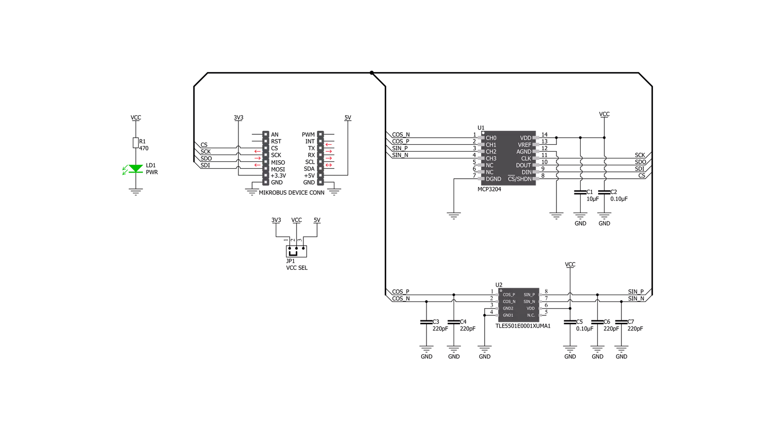
TMR Angle Click is based on the TLE5501, an analog TMR-based angle sensor from Infineon Technologies for any kind of angular position sensing from Infineon, and the MCP3204, a converter with SPI serial interface from Microchip. Regarding the TLE5501, the application fields range from steering angle applications with the highest functional safety requirements to motors for wipers, pumps and actuators and electric motors in general. TLE5501 is dedicated to any automotive but also industrial and consumer applications like robotics or gimbal. Some of its key features include large output signals of up to 0.37 V/V for easy analog value readout, discrete bridge with differential sine and cosine output, a very low supply current < 2.5 mA, a magnetic field range 20 mT to 100 mT and a typ. angle error < 1.0° (over the whole temperature and lifetime profile). It has been primarily designed for safety. One major benefit of the Infineon TMR technology is its
high sensing sensitivity coming with a high output voltage. So unlike other technologies, a TMR based sensor does not require any additional internal amplifier. Thus the sensor can be connected directly to the microcontroller without any further amplification – saving costs for the end customer. There is yet another cost saving aspect of Infineon’s TMR technology. TMR shows a very low temperature drift reducing external calibration and compensation efforts. In addition, the TMR technology is also well known for its low current consumption. When it comes to reading the output analog value, the MCP3204 is used – a 4-Channel A/D converter with SPI serial interface, from Microchip, it is ideally suited for sensor interface, process control, data acquisition and battery operated systems. It has a 12-bit resolution, and it is programmable to provide two pseudo-differential input pairs or four single-ended inputs. Configuration is done as part of the serial
command before each conversion begins. When used in the pseudodifferential mode, each channel pair (i.e., CH0 and CH1, CH2 and CH3 etc.) On this Click board™ the output sin and cos signals are wired as a pseudo-differential input signals to the MCP3204. Communication with the devices is accomplished using a simple serial interface compatible with the SPI protocol. The devices are capable of conversion rates of up to 100 ksps. The MCP3204/3208 devices operate over a broad voltage range (2.7V - 5.5V). This Click board™ can operate with either 3.3V or 5V logic voltage levels selected via the VCC SEL jumper. This way, both 3.3V and 5V capable MCUs can use the communication lines properly. Also, this Click board™ comes equipped with a library containing easy-to-use functions and an example code that can be used as a reference for further development.


Features overview
Development board
EasyAVR v8 is a development board designed to rapidly develop embedded applications based on 8-bit AVR microcontrollers (MCUs). Redesigned from the ground up, EasyAVR v8 offers a familiar set of standard features, as well as some new and unique features standard for the 8th generation of development boards: programming and debugging over the WiFi network, connectivity provided by USB-C connectors, support for a wide range of different MCUs, and more. The development board is designed so that the developer has everything that might be needed for the application development, following the Swiss Army knife concept: a highly advanced programmer/debugger module, a reliable power supply module, and a USB-UART connectivity option. EasyAVR v8 board offers several different DIP sockets, covering a wide range of 8-bit AVR MCUs, from the smallest
AVR MCU devices with only eight pins, all the way up to 40-pin "giants". The development board supports the well-established mikroBUS™ connectivity standard, offering five mikroBUS™ sockets, allowing access to a huge base of Click boards™. EasyAVR v8 offers two display options, allowing even the basic 8-bit AVR MCU devices to utilize them and display graphical or textual content. One of them is the 1x20 graphical display connector, compatible with the familiar Graphical Liquid Crystal Display (GLCD) based on the KS108 (or compatible) display driver, and EasyTFT board that contains TFT Color Display MI0283QT-9A, which is driven by ILI9341 display controller, capable of showing advanced graphical content. The other option is the 2x16 character LCD module, a four-bit display module with an embedded character-based display controller. It
requires minimal processing power from the host MCU for its operation. There is a wide range of useful interactive options at the disposal: high-quality buttons with selectable press levels, LEDs, pull-up/pulldown DIP switches, and more. All these features are packed on a single development board, which uses innovative manufacturing technologies, delivering a fluid and immersive working experience. The EasyAVR v8 development board is also integral to the MIKROE rapid development ecosystem. Natively supported by the MIKROE Software toolchain, backed up by hundreds of different Click board™ designs with their number growing daily, it covers many different prototyping and development aspects, thus saving precious development time.

Microcontroller Overview
MCU Card / MCU

Architecture
AVR
MCU Memory (KB)
128
Silicon Vendor
Microchip
Pin count
40
RAM (Bytes)
16384
Used MCU Pins
mikroBUS™ mapper
Take a closer look
Click board™ Schematic
Step by step
Project assembly

Start by selecting your development board and Click board™. Begin with the EasyAVR v8 as your development board.


Software Support
Library Description
This library contains API for TMR Angle Click driver.
Key functions:
tmrangle_init_sensor_data- Function read and stores negative and positive, sine and cosine parameters datatmrangle_calibration_find_param- This function will extract the maximum, minimum voltage levels, amplitude, offset, and orthogonalitytmrangle_get_calib_angle- Function calculates the calibrated angle in degrees and this structure holds the current sensor calibration parameters.
Open Source
Code example
The complete application code and a ready-to-use project are available through the NECTO Studio Package Manager for direct installation in the NECTO Studio. The application code can also be found on the MIKROE GitHub account.
/*!
 * \file
 * \brief TMRAngle Click example
 *
 * # Description
 * This application collects data from the sensor, calculates it, and then logs
 * the results.
 *
 * The demo application is composed of two sections :
 *
 * ## Application Init
 * Initializes driver, and also write log.
 *
 * ## Application Task
 * Reads angle value in degrees.
 * Results are being sent to the Usart Terminal where you can track their changes.
 * All data logs write on usb uart changes for every 1 sec.
 *
 *
 * \author MikroE Team
 *
 */
// ------------------------------------------------------------------- INCLUDES

#include "board.h"
#include "log.h"
#include "tmrangle.h"

// ------------------------------------------------------------------ VARIABLES

static tmrangle_t tmrangle;
static log_t logger;

// ------------------------------------------------------ APPLICATION FUNCTIONS

void application_init ( void )
{
    log_cfg_t log_cfg;
    tmrangle_cfg_t cfg;

    /**
     * Logger initialization.
     * Default baud rate: 115200
     * Default log level: LOG_LEVEL_DEBUG
     * @note If USB_UART_RX and USB_UART_TX
     * are defined as HAL_PIN_NC, you will
     * need to define them manually for log to work.
     * See @b LOG_MAP_USB_UART macro definition for detailed explanation.
     */
    LOG_MAP_USB_UART( log_cfg );
    log_init( &logger, &log_cfg );
    log_info( &logger, "---- Application Init ----" );

    //  Click initialization.

    tmrangle_cfg_setup( &cfg );
    TMRANGLE_MAP_MIKROBUS( cfg, MIKROBUS_1 );
    tmrangle_init( &tmrangle, &cfg );

}

void application_task ( void )
{
    float angle;
    trigonometry_t trig_set;
    tmrangle_calib_data_t calibration_store_params;
    tmrangle_init_sensor_data( &tmrangle );

    trig_set.max_diff_sin = TMRANGLE_MAX_DIFF_SIN;
    trig_set.max_diff_cos = TMRANGLE_MAX_DIFF_COS;
    trig_set.min_diff_sin = TMRANGLE_MIN_DIFF_SIN;
    trig_set.min_diff_cos = TMRANGLE_MIN_DIFF_COS;
    trig_set.sin_45 = TMRANGLE_SIN_45;
    trig_set.cos_45 = TMRANGLE_COS_45;
    trig_set.sin_135 = TMRANGLE_SIN_135;
    trig_set.cos_135 = TMRANGLE_COS_135;

    tmrangle_init_calib_data( &tmrangle, &calibration_store_params, &trig_set );
    tmrangle_calibration_find_param( &tmrangle, &calibration_store_params );

    angle = tmrangle_get_calib_angle( &tmrangle, &calibration_store_params );

    log_printf( &logger, "Angle is %f deg\r\n", angle );

    Delay_ms ( 1000 );
}

int main ( void )
{
    /* Do not remove this line or clock might not be set correctly. */
    #ifdef PREINIT_SUPPORTED
    preinit();
    #endif

    application_init( );

    for ( ; ; )
    {
        application_task( );
    }

    return 0;
}


// ------------------------------------------------------------------------ END


