Control your projects easily with CTHS15CIC05 and STM32F031K6
Ignite action!

Published Oct 01, 2024
Click board™
Button Power Click
Dev. board
Nucleo 32 with STM32F031K6 MCU
Compiler
NECTO Studio
MCU
STM32F031K6
Easily control device states using the intuitive POWER button, providing seamless on/off functionality tailored to your needs
A
A
Hardware Overview
How does it work?
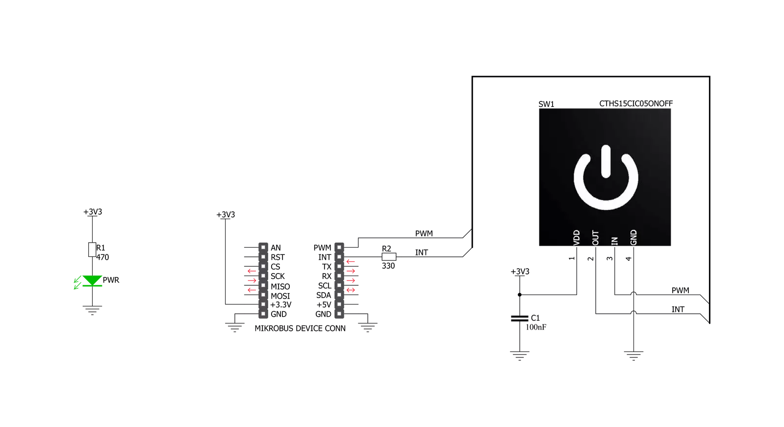
Button Power Click is based on the CTHS15CIC05ONOFF, a capacitive touch sensor display by VCC (Visual Communications Company). This sensor is an all-in-one solution, providing capacitive touch sensing in an appealing housing with the backlit power symbol icon on the top. A minimum number of pins is used on this device: only four pins are exposed to the user. Two more pins are used besides the power supply pins (VCC and GND). The touch detection is indicated by a HIGH logic level on the OUT pin of the CTHS15CIC05ONOFF sensor, while the IN pin is used as the power supply for two internal LEDs, which are connected in the common cathode configuration. The forward voltage of the LEDs is typically 3.2V. The OUT
pin of the sensor is routed to the INT pin of the mikroBUS™, while the IN pin of the sensor is routed to the PWM pin of the mikroBUS™. The power symbol icon on the top of the touch sensor is visible even when the backlight is off, thanks to the LEXAN™ polycarbonate film with an inverse print of the icon placed on top of the sensor. When the internal LEDs are turned ON, the light will pass through the translucent power symbol icon, resulting in a uniformly lit power symbol icon. An interesting lighting effect can be designed when touched by applying a PWM signal to the IN pin. The sensor IC, the sensing pad, and two integrated LEDs are enclosed in a small square casing, measuring 15mm by 15mm by 11mm. It forms a compact and robust touch button, which has
many advantages over a mechanical button: it is not subject to wear since there are no moving parts, it does not exhibit any bouncing or chattering effect, it is durable and resistant to weather elements, and more. However, it can’t be used to close an electrical circuit, only to produce a logic signal translated to appropriate action by the host MCU. The sensor can be operated even with wet hands or while using certain gloves. The touch sensor can also be placed behind a clear glass or a plastic layer, such as polycarbonate or acrylic, up to 3mm thick. Although the sensor will perform self-calibration after being powered, it is best to test its functionality in these cases if the position will be fixed.


Features overview
Development board
Nucleo 32 with STM32F031K6 MCU board provides an affordable and flexible platform for experimenting with STM32 microcontrollers in 32-pin packages. Featuring Arduino™ Nano connectivity, it allows easy expansion with specialized shields, while being mbed-enabled for seamless integration with online resources. The
board includes an on-board ST-LINK/V2-1 debugger/programmer, supporting USB reenumeration with three interfaces: Virtual Com port, mass storage, and debug port. It offers a flexible power supply through either USB VBUS or an external source. Additionally, it includes three LEDs (LD1 for USB communication, LD2 for power,
and LD3 as a user LED) and a reset push button. The STM32 Nucleo-32 board is supported by various Integrated Development Environments (IDEs) such as IAR™, Keil®, and GCC-based IDEs like AC6 SW4STM32, making it a versatile tool for developers.

Microcontroller Overview
MCU Card / MCU

Architecture
ARM Cortex-M0
MCU Memory (KB)
32
Silicon Vendor
STMicroelectronics
Pin count
32
RAM (Bytes)
4096
You complete me!
Accessories
Click Shield for Nucleo-32 is the perfect way to expand your development board's functionalities with STM32 Nucleo-32 pinout. The Click Shield for Nucleo-32 provides two mikroBUS™ sockets to add any functionality from our ever-growing range of Click boards™. We are fully stocked with everything, from sensors and WiFi transceivers to motor control and audio amplifiers. The Click Shield for Nucleo-32 is compatible with the STM32 Nucleo-32 board, providing an affordable and flexible way for users to try out new ideas and quickly create prototypes with any STM32 microcontrollers, choosing from the various combinations of performance, power consumption, and features. The STM32 Nucleo-32 boards do not require any separate probe as they integrate the ST-LINK/V2-1 debugger/programmer and come with the STM32 comprehensive software HAL library and various packaged software examples. This development platform provides users with an effortless and common way to combine the STM32 Nucleo-32 footprint compatible board with their favorite Click boards™ in their upcoming projects.

Used MCU Pins
mikroBUS™ mapper
Take a closer look
Click board™ Schematic
Step by step
Project assembly

Start by selecting your development board and Click board™. Begin with the Nucleo 32 with STM32F031K6 MCU as your development board.


Track your results in real time
Application Output
1. Application Output - In Debug mode, the 'Application Output' window enables real-time data monitoring, offering direct insight into execution results. Ensure proper data display by configuring the environment correctly using the provided tutorial.

2. UART Terminal - Use the UART Terminal to monitor data transmission via a USB to UART converter, allowing direct communication between the Click board™ and your development system. Configure the baud rate and other serial settings according to your project's requirements to ensure proper functionality. For step-by-step setup instructions, refer to the provided tutorial.

3. Plot Output - The Plot feature offers a powerful way to visualize real-time sensor data, enabling trend analysis, debugging, and comparison of multiple data points. To set it up correctly, follow the provided tutorial, which includes a step-by-step example of using the Plot feature to display Click board™ readings. To use the Plot feature in your code, use the function: plot(*insert_graph_name*, variable_name);. This is a general format, and it is up to the user to replace 'insert_graph_name' with the actual graph name and 'variable_name' with the parameter to be displayed.

Software Support
Library Description
This library contains API for Button Power Click driver.
Key functions:
buttonpower_pwm_stop- This function stops the PWM moudle outputbuttonpower_pwm_start- This function starts the PWM moudle outputbuttonpower_get_button_state- This function reads the digital signal from the INT pin which tells us whether the button has been pressed or not
Open Source
Code example
The complete application code and a ready-to-use project are available through the NECTO Studio Package Manager for direct installation in the NECTO Studio. The application code can also be found on the MIKROE GitHub account.
/*!
 * @file main.c
 * @brief Button Power Click Example.
 *
 * # Description
 * This example showcases how to initialize and use the whole family of Button Clicks.
 * One library is used for every single one of them. They are simple touch detectors which send
 * a pressed/released signal and receive a PWM output which controls the backlight on the button.
 *
 * The demo application is composed of two sections :
 *
 * ## Application Init
 * This function initializes and configures the logger and Click modules.
 *
 * ## Application Task
 * This example first increases the backlight on the button and then decreases the intensity of the backlight. When the button is touched,
 * reports the event in the console using UART communication.
 *
 *
 * @author Nikola Peric
 *
 */

#include "board.h"
#include "log.h"
#include "buttonpower.h"

static buttonpower_t buttonpower;
static log_t logger;

void application_init ( void )
{
    log_cfg_t log_cfg;                   /**< Logger config object. */
    buttonpower_cfg_t buttonpower_cfg;   /**< Click config object. */

    /**
     * Logger initialization.
     * Default baud rate: 115200
     * Default log level: LOG_LEVEL_DEBUG
     * @note If USB_UART_RX and USB_UART_TX
     * are defined as HAL_PIN_NC, you will
     * need to define them manually for log to work.
     * See @b LOG_MAP_USB_UART macro definition for detailed explanation.
     */
    LOG_MAP_USB_UART( log_cfg );
    log_init( &logger, &log_cfg );
    log_info( &logger, " Application Init " );

    // Click initialization.

    buttonpower_cfg_setup( &buttonpower_cfg );
    BUTTONPOWER_MAP_MIKROBUS( buttonpower_cfg, MIKROBUS_1 );
    err_t init_flag  = buttonpower_init( &buttonpower, &buttonpower_cfg );
    if ( PWM_ERROR == init_flag )
    {
        log_error( &logger, " Application Init Error. " );
        log_info( &logger, " Please, run program again... " );

        for ( ; ; );
    }
    Delay_ms ( 500 );

    buttonpower_pwm_start( &buttonpower );
    buttonpower_set_duty_cycle ( &buttonpower, 0.1 );

    log_info( &logger, " Application Task " );
}

void application_task ( void )
{
    static float duty_cycle;
    static uint8_t button_state;
    static uint8_t button_state_old;

    button_state = buttonpower_get_button_state( &buttonpower );

    if ( button_state && ( button_state != button_state_old ) )
    {
        log_printf( &logger, " <-- Button pressed --> \r\n" );
        for ( uint8_t n_cnt = 1; n_cnt <= 100; n_cnt++ )
        {
            duty_cycle = ( float ) n_cnt ;
            duty_cycle /= 100;
            buttonpower_set_duty_cycle( &buttonpower, duty_cycle );
            Delay_ms ( 10 );
        }
        button_state_old = button_state;
    }
    else if ( !button_state && ( button_state != button_state_old ) )
    {
        for ( uint8_t n_cnt = 100; n_cnt > 0; n_cnt-- )
        {
            duty_cycle = ( float ) n_cnt ;
            duty_cycle /= 100;
            buttonpower_set_duty_cycle( &buttonpower, duty_cycle );
            Delay_ms ( 10 );
        }
        button_state_old = button_state;
    }
}

int main ( void )
{
    /* Do not remove this line or clock might not be set correctly. */
    #ifdef PREINIT_SUPPORTED
    preinit();
    #endif

    application_init( );

    for ( ; ; )
    {
        application_task( );
    }

    return 0;
}

// ------------------------------------------------------------------------ END
Additional Support
Resources
Category:Capacitive


