Ensure stable and protected power delivery with HS2950P and STM32F031K6
Load protection HotSwitch® for various load conditions

Published Oct 01, 2024
Click board™
Current Limit 10 Click
Dev. board
Nucleo 32 with STM32F031K6 MCU
Compiler
NECTO Studio
MCU
STM32F031K6
Keep your electronic device safe by controlling the amount of electrical current it uses and protecting it from voltage-related issues
A
A
Hardware Overview
How does it work?
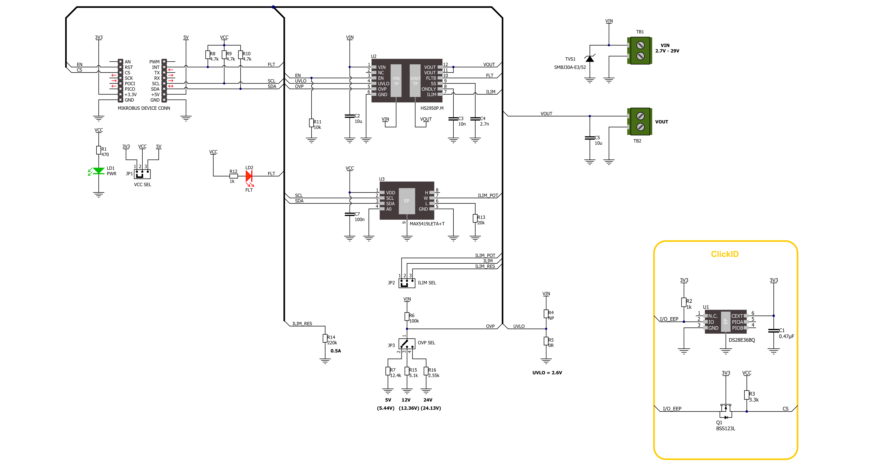
Current Limit 10 Click is based on the HS2950P, a load protection HotSwitch from Semtech. It utilizes flexible and programmable protection features and can handle multiple fault conditions. During fault conditions, automatic output discharge will be activated, thus protecting the load, and the HS2950P will automatically restart from a fault condition. The under-voltage lockout threshold is set to the default position (2.6V). The overvoltage protection can be externally set over the OVP SEL jumper, choosing between values 5.44V, 12.36V,
and 24.13V. The OVP is set by default to 5.44V. The current limit threshold can be set over the MAX5419, a nonvolatile digital potentiometer from Analog Devices. You can also choose the onboard external resistor for a fixed 0.5A value. The selection can be made over the ILIM SEL jumper. The soft start time is set to 0.32 ms, and the turn-on delay is set to 4 ms. Current Limit 10 Click uses a standard 2-wire I2C interface of the MAX5419 to allow the host MCU to set the limit threshold. The HS2950P will alert the host MCU when the fault
condition occurs over the FLT pin, along with the FLT LED indicator. Finally, you can turn off the current limiter over the enable EN pin. This Click board™ can operate with either 3.3V or 5V logic voltage levels selected via the VCC SEL jumper. This way, both 3.3V and 5V capable MCUs can use the communication lines properly. Also, this Click board™ comes equipped with a library containing easy-to-use functions and an example code that can be used as a reference for further development.

Features overview
Development board
Nucleo 32 with STM32F031K6 MCU board provides an affordable and flexible platform for experimenting with STM32 microcontrollers in 32-pin packages. Featuring Arduino™ Nano connectivity, it allows easy expansion with specialized shields, while being mbed-enabled for seamless integration with online resources. The
board includes an on-board ST-LINK/V2-1 debugger/programmer, supporting USB reenumeration with three interfaces: Virtual Com port, mass storage, and debug port. It offers a flexible power supply through either USB VBUS or an external source. Additionally, it includes three LEDs (LD1 for USB communication, LD2 for power,
and LD3 as a user LED) and a reset push button. The STM32 Nucleo-32 board is supported by various Integrated Development Environments (IDEs) such as IAR™, Keil®, and GCC-based IDEs like AC6 SW4STM32, making it a versatile tool for developers.

Microcontroller Overview
MCU Card / MCU

Architecture
ARM Cortex-M0
MCU Memory (KB)
32
Silicon Vendor
STMicroelectronics
Pin count
32
RAM (Bytes)
4096
You complete me!
Accessories
Click Shield for Nucleo-32 is the perfect way to expand your development board's functionalities with STM32 Nucleo-32 pinout. The Click Shield for Nucleo-32 provides two mikroBUS™ sockets to add any functionality from our ever-growing range of Click boards™. We are fully stocked with everything, from sensors and WiFi transceivers to motor control and audio amplifiers. The Click Shield for Nucleo-32 is compatible with the STM32 Nucleo-32 board, providing an affordable and flexible way for users to try out new ideas and quickly create prototypes with any STM32 microcontrollers, choosing from the various combinations of performance, power consumption, and features. The STM32 Nucleo-32 boards do not require any separate probe as they integrate the ST-LINK/V2-1 debugger/programmer and come with the STM32 comprehensive software HAL library and various packaged software examples. This development platform provides users with an effortless and common way to combine the STM32 Nucleo-32 footprint compatible board with their favorite Click boards™ in their upcoming projects.

Used MCU Pins
mikroBUS™ mapper
Take a closer look
Click board™ Schematic
Step by step
Project assembly

Start by selecting your development board and Click board™. Begin with the Nucleo 32 with STM32F031K6 MCU as your development board.


Software Support
Library Description
This library contains API for Current Limit 10 Click driver.
Key functions:
currentlimit10_set_limit- This function sets the desired current limit threshold using the I2C serial interface.currentlimit10_get_fault- This function gets the state of the fault flag to indicate overcurrent, overtemperature, or reverse-voltage conditions.currentlimit10_enable- This function turns on the power switch and enables the internal MOSFET.
Open Source
Code example
The complete application code and a ready-to-use project are available through the NECTO Studio Package Manager for direct installation in the NECTO Studio. The application code can also be found on the MIKROE GitHub account.
/*!
* @file main.c
* @brief Current Limit 10 Click example
*
* # Description
* This library contains API for the Current Limit 10 Click driver.
* This driver provides the functions to set the current limiting conditions
* in order to provide the threshold of the fault conditions.
*
* The demo application is composed of two sections :
*
* ## Application Init
* Initialization of I2C module and log UART.
* After driver initialization, the app executes a default configuration
* and and sets the current limit threshold of 750 mA.
*
* ## Application Task
* This example demonstrates the use of the Current Limit 10 Click board.
* The demo application checks the fault flag for overcurrent conditions.
* Results are being sent to the UART Terminal, where you can track their changes.
*
* @author Nenad Filipovic
*
*/
#include "board.h"
#include "log.h"
#include "currentlimit10.h"
static currentlimit10_t currentlimit10;
static log_t logger;
void application_init ( void )
{
log_cfg_t log_cfg; /**< Logger config object. */
currentlimit10_cfg_t currentlimit10_cfg; /**< Click config object. */
/**
* Logger initialization.
* Default baud rate: 115200
* Default log level: LOG_LEVEL_DEBUG
* @note If USB_UART_RX and USB_UART_TX
* are defined as HAL_PIN_NC, you will
* need to define them manually for log to work.
* See @b LOG_MAP_USB_UART macro definition for detailed explanation.
*/
LOG_MAP_USB_UART( log_cfg );
log_init( &logger, &log_cfg );
log_info( &logger, " Application Init " );
// Click initialization.
currentlimit10_cfg_setup( ¤tlimit10_cfg );
CURRENTLIMIT10_MAP_MIKROBUS( currentlimit10_cfg, MIKROBUS_1 );
if ( I2C_MASTER_ERROR == currentlimit10_init( ¤tlimit10, ¤tlimit10_cfg ) )
{
log_error( &logger, " Communication init." );
for ( ; ; );
}
if ( CURRENTLIMIT10_ERROR == currentlimit10_default_cfg ( ¤tlimit10 ) )
{
log_error( &logger, " Default configuration." );
for ( ; ; );
}
if ( CURRENTLIMIT10_ERROR == currentlimit10_set_limit( ¤tlimit10, 0.75 ) )
{
log_error( &logger, " Current limit threshold." );
for ( ; ; );
}
log_info( &logger, " Application Task " );
Delay_ms ( 100 );
}
void application_task ( void )
{
if ( CURRENTLIMIT10_FAULT_FLAG == currentlimit10_get_fault( ¤tlimit10 ) )
{
log_printf( &logger, "Fault flag: Overcurrent\r\n" );
}
else
{
log_printf( &logger, " Current limit is 0.75 A\r\n" );
}
Delay_ms ( 1000 );
}
int main ( void )
{
/* Do not remove this line or clock might not be set correctly. */
#ifdef PREINIT_SUPPORTED
preinit();
#endif
application_init( );
for ( ; ; )
{
application_task( );
}
return 0;
}
// ------------------------------------------------------------------------ END
Additional Support
Resources
Category:Power Switch


