Bring a new level of control to your projects with DH101ALSMT001 and STM32F031K6
Thumbs up to precision: Perfecting user experience

Published Oct 01, 2024
Click board™
Thumbwheel Click
Dev. board
Nucleo 32 with STM32F031K6 MCU
Compiler
NECTO Studio
MCU
STM32F031K6
From concept to execution, find out how 10-position thumbwheel switch can lead you to design excellence
A
A
Hardware Overview
How does it work?
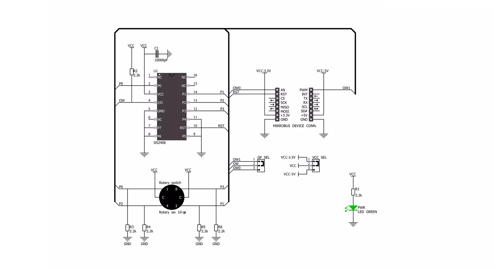
Thumbwheel Click is based on the DH101ALSMT001, 10-position thumb wheel switch from Apem. The combination of copper alloy, hard gold, stainless steel, and plastic housing makes it very robust. The thumb wheel switch has four basic pins as outputs on this Click board™, pulled down. By selecting one of the positions, the wheel switch internally connects up to four of those pins to a common VCC. The combination of the pulled-up pins can be read, thus letting the host MCU know what position of the Thumbwheel click is
selected. To make things easier, this Click board™ features the DS2408, a 1-Wire 8-channel addressable switch from Analog Devices. It is a programmable I/O device with open drain outputs that can individually capture the state changes at the PIO inputs for interrogation by the bus master. The four output pins from the DH1 are connected to the corresponding IO pins of the DS2408. The DS2408 uses a 1-Wire interface with a single digital signal at 15.3Kbls, or 100Kbps, to communicate to the host MCU. For communication, you can
choose between OW0 or OW1pins of the mikroBUS™ socket over the GP SEL (OW1 selected by default). The DS2408 has a unique factory-lasered 64-bit registration number, so more Thumbwheel Clicks can be used on a single bus. This Click board™ can operate with either 3.3V or 5V logic voltage levels selected via the VCC SEL jumper. Also, this Click board™ comes equipped with a library containing easy-to-use functions and an example code that can be used as a reference for further development.


Features overview
Development board
Nucleo 32 with STM32F031K6 MCU board provides an affordable and flexible platform for experimenting with STM32 microcontrollers in 32-pin packages. Featuring Arduino™ Nano connectivity, it allows easy expansion with specialized shields, while being mbed-enabled for seamless integration with online resources. The
board includes an on-board ST-LINK/V2-1 debugger/programmer, supporting USB reenumeration with three interfaces: Virtual Com port, mass storage, and debug port. It offers a flexible power supply through either USB VBUS or an external source. Additionally, it includes three LEDs (LD1 for USB communication, LD2 for power,
and LD3 as a user LED) and a reset push button. The STM32 Nucleo-32 board is supported by various Integrated Development Environments (IDEs) such as IAR™, Keil®, and GCC-based IDEs like AC6 SW4STM32, making it a versatile tool for developers.

Microcontroller Overview
MCU Card / MCU

Architecture
ARM Cortex-M0
MCU Memory (KB)
32
Silicon Vendor
STMicroelectronics
Pin count
32
RAM (Bytes)
4096
You complete me!
Accessories
Click Shield for Nucleo-32 is the perfect way to expand your development board's functionalities with STM32 Nucleo-32 pinout. The Click Shield for Nucleo-32 provides two mikroBUS™ sockets to add any functionality from our ever-growing range of Click boards™. We are fully stocked with everything, from sensors and WiFi transceivers to motor control and audio amplifiers. The Click Shield for Nucleo-32 is compatible with the STM32 Nucleo-32 board, providing an affordable and flexible way for users to try out new ideas and quickly create prototypes with any STM32 microcontrollers, choosing from the various combinations of performance, power consumption, and features. The STM32 Nucleo-32 boards do not require any separate probe as they integrate the ST-LINK/V2-1 debugger/programmer and come with the STM32 comprehensive software HAL library and various packaged software examples. This development platform provides users with an effortless and common way to combine the STM32 Nucleo-32 footprint compatible board with their favorite Click boards™ in their upcoming projects.

Used MCU Pins
mikroBUS™ mapper
Take a closer look
Click board™ Schematic
Step by step
Project assembly

Start by selecting your development board and Click board™. Begin with the Nucleo 32 with STM32F031K6 MCU as your development board.


Software Support
Library Description
This library contains API for Thumbwheel Click driver.
Key functions:
thumbwheel_get_position- This function gets the position of the rotary sprocket.
Open Source
Code example
The complete application code and a ready-to-use project are available through the NECTO Studio Package Manager for direct installation in the NECTO Studio. The application code can also be found on the MIKROE GitHub account.
/*!
 * @file main.c
 * @brief Thumbwheel Click Example.
 *
 * # Description
 * This example demonstrates the use of Thumbwheel Click board
 * by displaying the exact position of the rotary sprocket.
 *
 * The demo application is composed of two sections :
 *
 * ## Application Init
 * Initializes the driver and checks the communication.
 *
 * ## Application Task
 * Demonstrates the usage of thumbwheel_get_position function
 * which gives the exact position of the rotary sprocket.
 * The position will be displayed on the UART Terminal.
 *
 * @author Aleksandra Cvjeticanin
 *
 */

#include "board.h"
#include "log.h"
#include "thumbwheel.h"

static thumbwheel_t thumbwheel;
static log_t logger;

void application_init ( void )
{
    log_cfg_t log_cfg;  /**< Logger config object. */
    thumbwheel_cfg_t thumbwheel_cfg;  /**< Click config object. */

    /**
     * Logger initialization.
     * Default baud rate: 115200
     * Default log level: LOG_LEVEL_DEBUG
     * @note If USB_UART_RX and USB_UART_TX
     * are defined as HAL_PIN_NC, you will
     * need to define them manually for log to work.
     * See @b LOG_MAP_USB_UART macro definition for detailed explanation.
     */
    LOG_MAP_USB_UART( log_cfg );
    log_init( &logger, &log_cfg );
    log_info( &logger, " Application Init " );

    // Click initialization.
    thumbwheel_cfg_setup( &thumbwheel_cfg );
    THUMBWHEEL_MAP_MIKROBUS( thumbwheel_cfg, MIKROBUS_1 );
    if ( ONE_WIRE_ERROR == thumbwheel_init( &thumbwheel, &thumbwheel_cfg ) )
    {
        log_error( &logger, " Communication init." );
        for ( ; ; );
    }

    if ( THUMBWHEEL_ERROR == thumbwheel_check_communication ( &thumbwheel ) )
    {
        log_error( &logger, " Default configuration." );
        for ( ; ; );
    }

    log_info( &logger, " Application Task " );
}

void application_task ( void )
{
    static uint8_t old_position = 0xFF;
    uint8_t position;

    if ( ( THUMBWHEEL_OK == thumbwheel_get_position ( &thumbwheel, &position ) ) &&
         ( old_position != position ) )
    {
        log_printf( &logger, " Position: %u \r\n\n", ( uint16_t ) position );
        old_position = position;
    }
    Delay_ms ( 100 );
}

int main ( void )
{
    /* Do not remove this line or clock might not be set correctly. */
    #ifdef PREINIT_SUPPORTED
    preinit();
    #endif

    application_init( );

    for ( ; ; )
    {
        application_task( );
    }

    return 0;
}

// ------------------------------------------------------------------------ END
Additional Support
Resources
Category:Pushbutton/Switches


