Control and monitor four separate loads simultaneously with the 9913-05-20TR and EasyMx PRO v7 for STM32 MCUcard with STM32F746VGT6
Four high-performance SMD reed relays with high switching capabilities

Published May 21, 2024
Click board™
Relay 6 Click
Dev.Board
EasyMx PRO v7a for STM32
Compiler
NECTO Studio
MCU
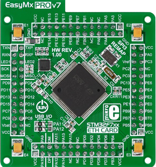
EasyMx PRO v7 for STM32 MCUcard with STM32F746VGT6
Accurately manage four individual loads in automated test equipment, instrumentation, and telecommunications applications.
A
A
Hardware Overview
How does it work?
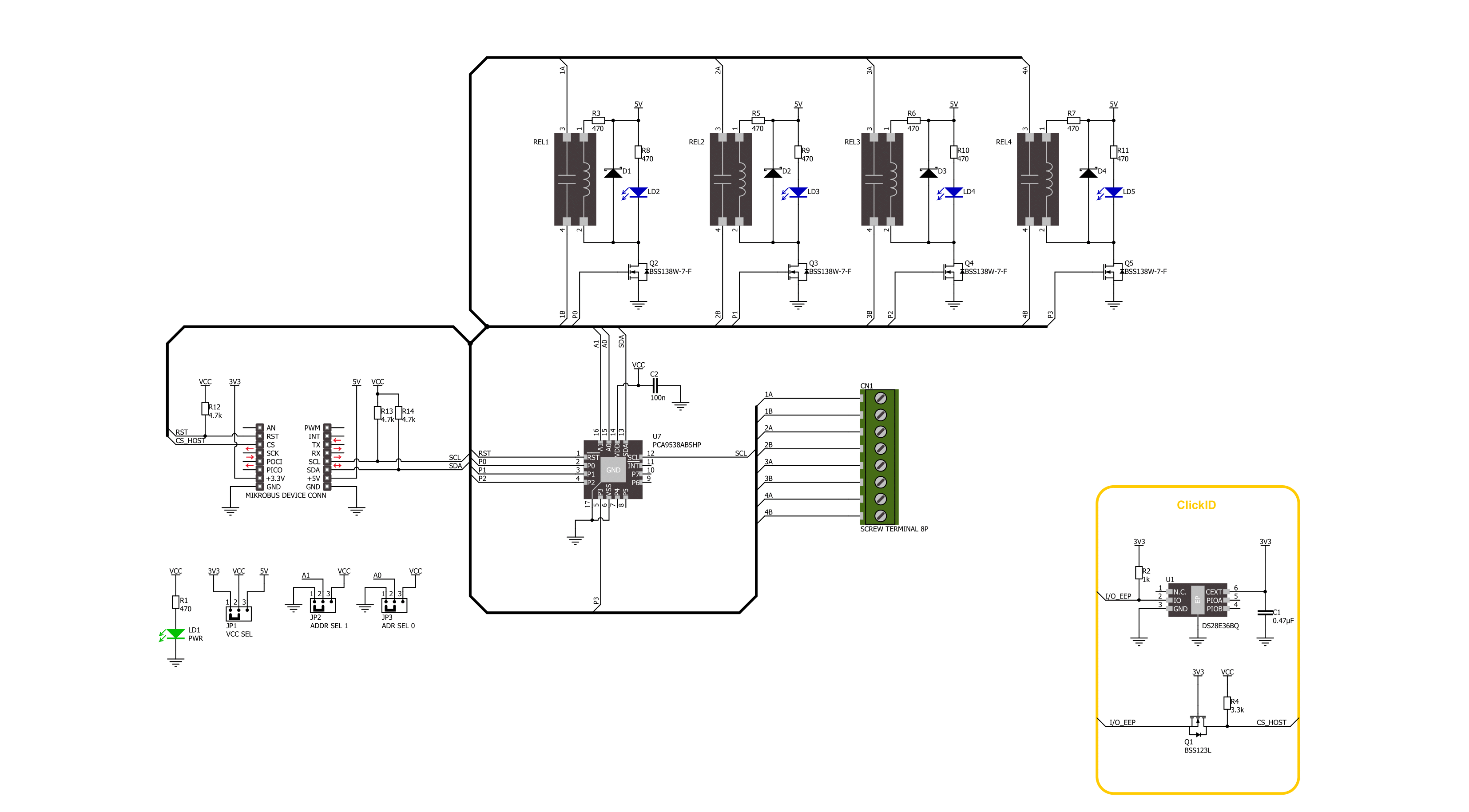
Relay 6 Click is based on the 9913-05-20TR, a reed relay from Coto Technology, a component known for its ultra-miniature SMD design, standing for the smallest footprint in the market. This Click board™ features four relays, each equipped with four terminals for load connections that are controlled via these relays. Beneath each relay is a blue LED indicator that illuminates to signal when the relay is active, serving as an operational status indicator. This setup provides clear and immediate feedback on the status of each relay, enhancing user control and system monitoring. This Click board™ is ideal for automated test equipment, instrumentation, and telecommunications applications, highlighting high reliability and long
life due to relays hermetically sealed contacts. The 9913-05-20TRs also feature a high insulation resistance of a minimum of 1011Ω and an external magnetic shield. Its electrical specifications include a coil voltage of 5VDC, a coil resistance of 200Ω, a single-pole single-throw normally open (SPST-NO, 1 Form A) contact form, with the contact current rating capped at 250mA and the switching voltage limited to 100VAC and 100VDC. Control and communication between the relays and the host MCU are managed via the PCA9538A port expander, which uses an I2C communication interface. This device supports both Standard and Fast modes, with frequencies up to 400kHz. The PCA9538A's I2C address can be configured
through the ADDR SEL jumpers, allowing flexible integration with various MCU systems. The PCA9538A also uses an RST pin that ensures the registers and I2C-bus state machine remain in their default settings until this pin is set to a HIGH logic state, where the device returns to normal operational status. This Click board™ can operate with either 3.3V or 5V logic voltage levels selected via the VCC SEL jumper. This way, both 3.3V and 5V capable MCUs can use the communication lines properly. Also, this Click board™ comes equipped with a library containing easy-to-use functions and an example code that can be used as a reference for further development.

Features overview
Development board
EasyMx PRO v7a for STM32 is the seventh generation of ARM development boards specially designed to develop embedded applications rapidly. It supports a wide range of 32-bit ARM microcontrollers from STMicroelectronics and a broad set of unique functions, such as the first-ever embedded debugger/programmer over USB-C. The development board is well organized and designed so that the end-user has all the necessary elements, such as switches, buttons, indicators, connectors, and others, in one place. With two different connectors for each port, EasyMx PRO v7afor STM32 allows you to connect accessory boards, sensors, and custom electronics more efficiently than ever. Each part of the EasyMx
PRO v7a for STM32 development board contains the components necessary for the most efficient operation of the same board. In addition to the advanced integrated CODEGRIP programmer/debugger module, which offers many valuable programming/debugging options and seamless integration with the Mikroe software environment, the board also includes a clean and regulated power supply block for the development board. It can use a wide range of external power sources, including an external 12V power supply, 7-23V AC or 9-32V DC via DC connector/screw terminals, and a power source via the USB Type-C (USB-C) connector. Communication options such as USB-UART, USB-HOST/DEVICE, CAN, and
Ethernet are also included, including the well-established mikroBUS™ standard, one display option for the TFT board line of products, and a standard TQFP socket for the seventh-generation MCU cards. This socket covers 32-bit ARM MCUs like STM32 Cortex-M3, -M7, and -M4 MCUs. EasyMx PRO v7afor STM32 is an integral part of the Mikroe ecosystem for rapid development. Natively supported by Mikroe software tools, it covers many aspects of prototyping and development thanks to a considerable number of different Click boards™ (over a thousand boards), the number of which is growing every day.

Microcontroller Overview
MCU Card / MCU
Type
7th Generation
Architecture
ARM Cortex-M7
MCU Memory (KB)
1024
Silicon Vendor
STMicroelectronics
Pin count
100
RAM (Bytes)
327680
Used MCU Pins
mikroBUS™ mapper
Take a closer look
Schematic
Step by step
Project assembly

Start by selecting your development board and Click board™. Begin with the EasyMx PRO v7a for STM32 as your development board.


Track your results in real time
Application Output
After pressing the "FLASH" button on the left-side panel, it is necessary to open the UART terminal to display the achieved results. By clicking on the Tools icon in the right-hand panel, multiple different functions are displayed, among which is the UART Terminal. Click on the offered "UART Terminal" icon.

Once the UART terminal is opened, the window takes on a new form. At the top of the tab are two buttons, one for adjusting the parameters of the UART terminal and the other for connecting the UART terminal. The tab's lower part is reserved for displaying the achieved results. Before connecting, the terminal has a Disconnected status, indicating that the terminal is not yet active. Before connecting, it is necessary to check the set parameters of the UART terminal. Click on the "OPTIONS" button.

In the newly opened UART Terminal Options field, we check if the terminal settings are correct, such as the set port and the Baud rate of UART communication. If the data is not displayed properly, it is possible that the Baud rate value is not set correctly and needs to be adjusted to 115200. If all the parameters are set correctly, click on "CONFIGURE".

The next step is to click on the "CONNECT" button, after which the terminal status changes from Disconnected to Connected in green, and the data is displayed in the Received data field.

Software Support
Library Description
This library contains API for Relay 6 Click driver.
Key functions:
relay6_reset_port_expander- Relay 6 reset port expander function.relay6_port_expander_write- Relay 6 port expander write register function.relay6_set_relay- Relay 6 set relay state function.
Open Source
Code example
This example can be found in NECTO Studio. Feel free to download the code, or you can copy the code below.
/*!
 * @file main.c
 * @brief Relay 6 Click example
 *
 * # Description
 * This example demonstrates the use of Relay 6 click board by toggling the relays state.
 *
 * The demo application is composed of two sections :
 *
 * ## Application Init
 * Initializes the driver and logger.
 *
 * ## Application Task
 * Switches all relays state every second and displays the state on the USB UART.
 *
 * @author Stefan Ilic
 *
 */

#include "board.h"
#include "log.h"
#include "relay6.h"

static relay6_t relay6;
static log_t logger;

void application_init ( void )
{
    log_cfg_t log_cfg;  /**< Logger config object. */
    relay6_cfg_t relay6_cfg;  /**< Click config object. */

    /**
     * Logger initialization.
     * Default baud rate: 115200
     * Default log level: LOG_LEVEL_DEBUG
     * @note If USB_UART_RX and USB_UART_TX
     * are defined as HAL_PIN_NC, you will
     * need to define them manually for log to work.
     * See @b LOG_MAP_USB_UART macro definition for detailed explanation.
     */
    LOG_MAP_USB_UART( log_cfg );
    log_init( &logger, &log_cfg );
    log_info( &logger, " Application Init " );

    // Click initialization.
    relay6_cfg_setup( &relay6_cfg );
    RELAY6_MAP_MIKROBUS( relay6_cfg, MIKROBUS_1 );
    if ( I2C_MASTER_ERROR == relay6_init( &relay6, &relay6_cfg ) )
    {
        log_error( &logger, " Communication init." );
        for ( ; ; );
    }

    if ( RELAY6_ERROR == relay6_default_cfg ( &relay6 ) )
    {
        log_error( &logger, " Default configuration." );
        for ( ; ; );
    }

    log_info( &logger, " Application Task " );
}

void application_task ( void )
{
    uint8_t relay_data;
    relay_data = RELAY6_RELAY1_PIN;

    log_printf( &logger, " Turning on only Relay 1 \r\n" );
    log_printf( &logger, " = = = = = = = = = = = = = \r\n" );
    relay6_set_relay( &relay6, relay_data, ~relay_data );
    relay_data <<= 1;
    Delay_ms( 1000 );

    log_printf( &logger, " Turning on only Relay 2 \r\n" );
    log_printf( &logger, " = = = = = = = = = = = = = \r\n" );
    relay6_set_relay( &relay6, relay_data, ~relay_data );
    relay_data <<= 1;
    Delay_ms( 1000 );

    log_printf( &logger, " Turning on only Relay 3 \r\n" );
    log_printf( &logger, " = = = = = = = = = = = = = \r\n" );
    relay6_set_relay( &relay6, relay_data, ~relay_data );
    relay_data <<= 1;
    Delay_ms( 1000 );

    log_printf( &logger, " Turning on only Relay 4 \r\n" );
    log_printf( &logger, " = = = = = = = = = = = = = \r\n" );
    relay6_set_relay( &relay6, relay_data, ~relay_data );
    relay_data <<= 1;
    Delay_ms( 1000 );

}

void main ( void )
{
    application_init( );

    for ( ; ; )
    {
        application_task( );
    }
}

// ------------------------------------------------------------------------ END


