Achieve current sensing up to 25A with LES 25-NP and STM32G474RE
Precise and isolated AC/DC/pulsed current measurement for industrial use
Published May 19, 2025
Click board™
Current Sens Click
Dev. board
Nucleo 64 with STM32G474RE MCU
Compiler
NECTO Studio
MCU
STM32G474RE
Measure AC, DC, and pulsed currents up to 25A perfect for UPS systems and industrial power monitoring
A
A
Hardware Overview
How does it work?
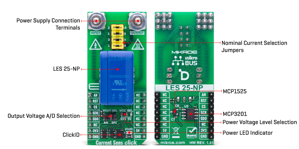
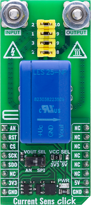
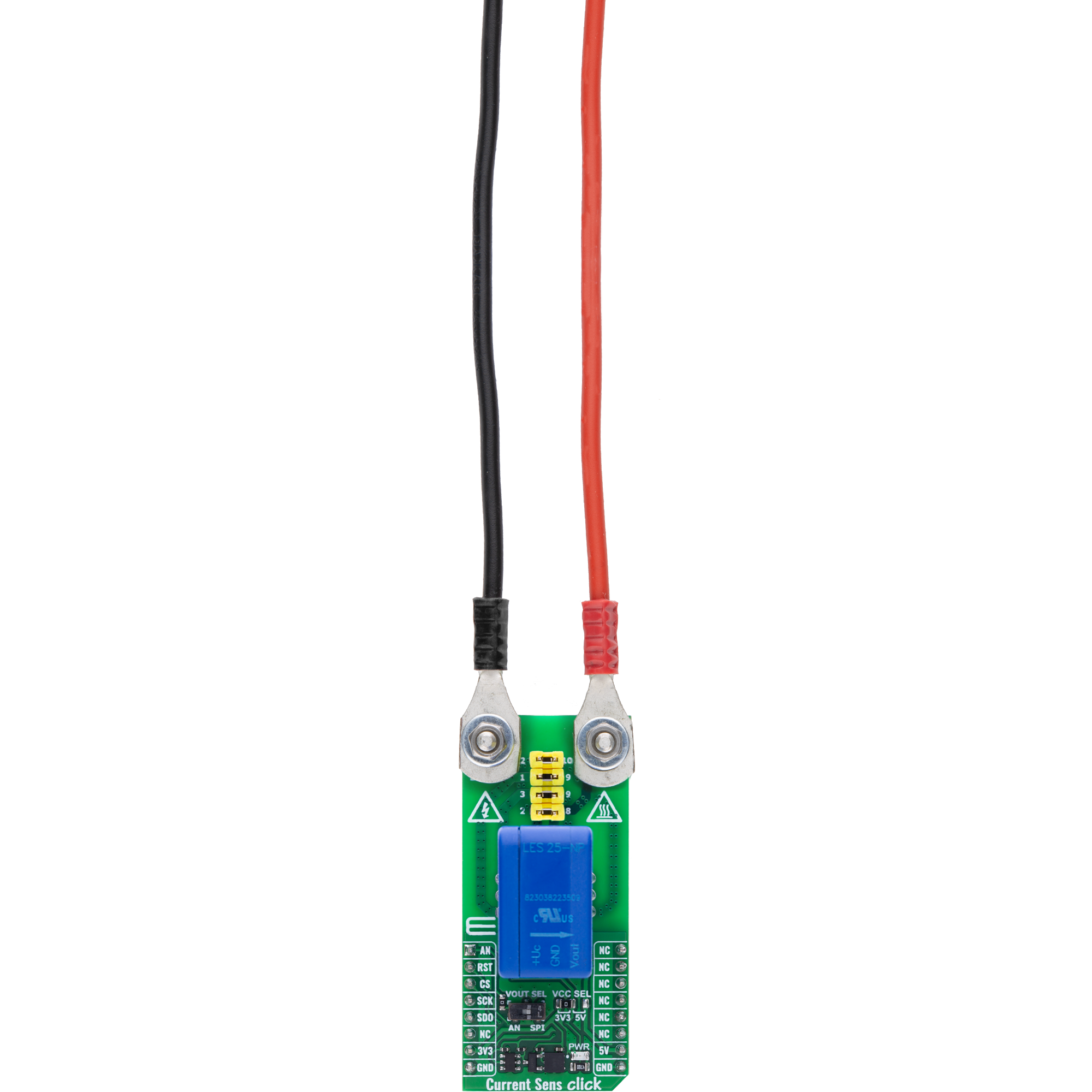
Current Sens Click is based on the LES 25-NP current transducer from LEM USA, a closed-loop, multi-range sensor capable of accurately detecting direct, alternating, and pulsed currents up to 25A. This device ensures galvanic isolation between the primary and secondary circuits, providing robust electrical safety and signal integrity. The LES 25-NP supports selectable output modes - either analog or digital - allowing for flexible integration into a wide range of systems. It operates on a unipolar DC supply voltage, simplifying power design requirements. With extremely low offset drift and strong immunity to rapid voltage transients (dv/dt), this sensor maintains reliable and consistent measurements even in electrically noisy environments. Engineered in compliance with multiple international safety and performance standards, including IEC 61800, IEC 62109, IEC 62477, and UL 508, Current Sens Click is well-suited for use in AC variable speed drives, servo
motor controllers, DC motor converters, battery-powered systems, UPS units, SMPS units, welding equipment, and solar inverter solutions. Just above the current sensor on the board, there is a dedicated jumper section that allows adjustment of the nominal primary current. The LES 25-NP sensor supports three different primary connection configurations, enabling precise measurement of either the full, half, or one-third of the primary current, which significantly enhances resolution in low-current applications. Each conductor exhibits a primary resistance of 0.72mΩ. The datasheet provides a reference table that outlines how different jumper settings define the primary nominal RMS current and corresponding primary resistance, based on the selected number of primary turns. As mentioned, the LES 25-NP's output signal can be converted to a digital value using MCP3201, a successive approximation A/D converter with a 12-bit resolution from Microchip, using an SPI
compatible interface, or sent directly to an analog pin of the mikroBUS™ socket labeled as AN. Selection can be performed via an onboard SMD switch labeled VOUT SEL, placing it in an appropriate position marked as AN or SPI. To provide the required reference voltage for accurate digital conversion, the MCP3201 A/D converter uses the MCP1525, a precision 2.5V voltage reference from Microchip. This ensures stable and consistent reference conditions, allowing the MCP3201 to deliver reliable 12-bit digital output when measuring the analog signal from the LES 25-NP sensor. This Click board™ can operate with either 3.3V or 5V logic voltage levels selected via the VCC SEL jumper. This way, both 3.3V and 5V capable MCUs can use the communication lines properly. Also, this Click board™ comes equipped with a library containing easy-to-use functions and an example code that can be used as a reference for further development.
 DO NOT TOUCH THE BOARD WHILE THE EXTERNAL POWER SUPPLY IS ON!
NOTE: This Click board™ needs to be used by trained personnel only while applying high voltages. Special care should be taken when working with hazardous voltage levels.
Features overview
Development board
Nucleo-64 with STM32G474R MCU offers a cost-effective and adaptable platform for developers to explore new ideas and prototype their designs. This board harnesses the versatility of the STM32 microcontroller, enabling users to select the optimal balance of performance and power consumption for their projects. It accommodates the STM32 microcontroller in the LQFP64 package and includes essential components such as a user LED, which doubles as an ARDUINO® signal, alongside user and reset push-buttons, and a 32.768kHz crystal oscillator for precise timing operations. Designed with expansion and flexibility in mind, the Nucleo-64 board features an ARDUINO® Uno V3 expansion connector and ST morpho extension pin
headers, granting complete access to the STM32's I/Os for comprehensive project integration. Power supply options are adaptable, supporting ST-LINK USB VBUS or external power sources, ensuring adaptability in various development environments. The board also has an on-board ST-LINK debugger/programmer with USB re-enumeration capability, simplifying the programming and debugging process. Moreover, the board is designed to simplify advanced development with its external SMPS for efficient Vcore logic supply, support for USB Device full speed or USB SNK/UFP full speed, and built-in cryptographic features, enhancing both the power efficiency and security of projects. Additional connectivity is
provided through dedicated connectors for external SMPS experimentation, a USB connector for the ST-LINK, and a MIPI® debug connector, expanding the possibilities for hardware interfacing and experimentation. Developers will find extensive support through comprehensive free software libraries and examples, courtesy of the STM32Cube MCU Package. This, combined with compatibility with a wide array of Integrated Development Environments (IDEs), including IAR Embedded Workbench®, MDK-ARM, and STM32CubeIDE, ensures a smooth and efficient development experience, allowing users to fully leverage the capabilities of the Nucleo-64 board in their projects.

Microcontroller Overview
MCU Card / MCU

Architecture
ARM Cortex-M4
MCU Memory (KB)
512
Silicon Vendor
STMicroelectronics
Pin count
64
RAM (Bytes)
128k
You complete me!
Accessories
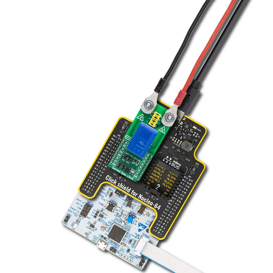
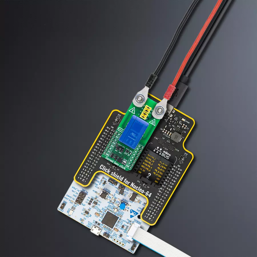
Click Shield for Nucleo-64 comes equipped with two proprietary mikroBUS™ sockets, allowing all the Click board™ devices to be interfaced with the STM32 Nucleo-64 board with no effort. This way, Mikroe allows its users to add any functionality from our ever-growing range of Click boards™, such as WiFi, GSM, GPS, Bluetooth, ZigBee, environmental sensors, LEDs, speech recognition, motor control, movement sensors, and many more. More than 1537 Click boards™, which can be stacked and integrated, are at your disposal. The STM32 Nucleo-64 boards are based on the microcontrollers in 64-pin packages, a 32-bit MCU with an ARM Cortex M4 processor operating at 84MHz, 512Kb Flash, and 96KB SRAM, divided into two regions where the top section represents the ST-Link/V2 debugger and programmer while the bottom section of the board is an actual development board. These boards are controlled and powered conveniently through a USB connection to program and efficiently debug the Nucleo-64 board out of the box, with an additional USB cable connected to the USB mini port on the board. Most of the STM32 microcontroller pins are brought to the IO pins on the left and right edge of the board, which are then connected to two existing mikroBUS™ sockets. This Click Shield also has several switches that perform functions such as selecting the logic levels of analog signals on mikroBUS™ sockets and selecting logic voltage levels of the mikroBUS™ sockets themselves. Besides, the user is offered the possibility of using any Click board™ with the help of existing bidirectional level-shifting voltage translators, regardless of whether the Click board™ operates at a 3.3V or 5V logic voltage level. Once you connect the STM32 Nucleo-64 board with our Click Shield for Nucleo-64, you can access hundreds of Click boards™, working with 3.3V or 5V logic voltage levels.

Used MCU Pins
mikroBUS™ mapper
Take a closer look
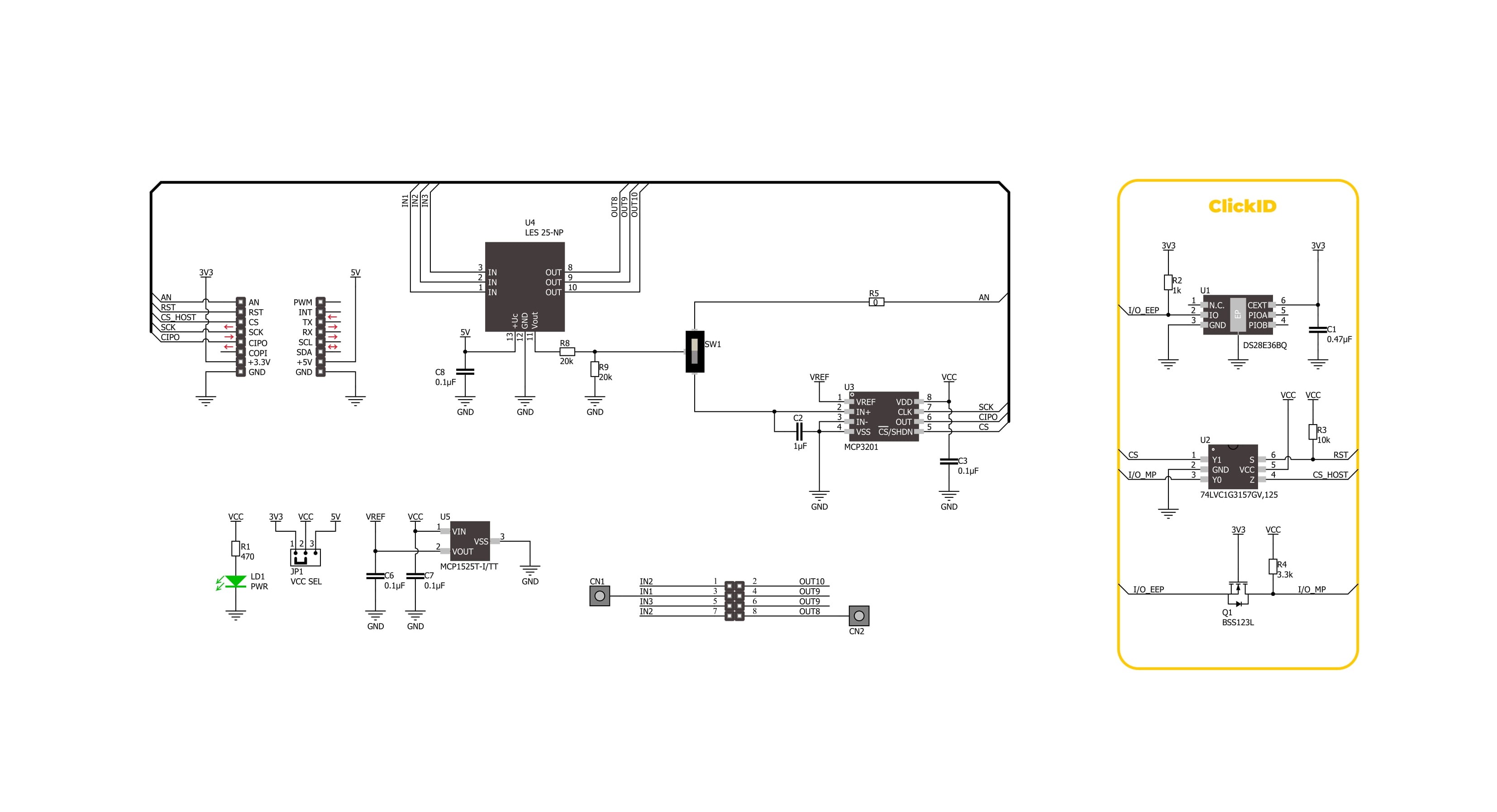
Click board™ Schematic
Step by step
Project assembly
Start by selecting your development board and Click board™. Begin with the Nucleo 64 with STM32G474RE MCU as your development board.


Software Support
Library Description
Current Sens Click demo application is developed using the NECTO Studio, ensuring compatibility with mikroSDK's open-source libraries and tools. Designed for plug-and-play implementation and testing, the demo is fully compatible with all development, starter, and mikromedia boards featuring a mikroBUS™ socket.
Example Description
This example demonstrates the use of Current Sens Click board by reading and displaying the input current measurements.
Key functions:
currentsens_cfg_setup- Config Object Initialization function.currentsens_init- Initialization function.currentsens_calib_offset- This function calibrates the zero current offset value.currentsens_calib_resolution- This function calibrates the data resolution at the known load current.currentsens_read_current- This function reads the input current level [A].
Application Init
Initializes the driver and calibrates the zero current offset and data resolution at 3A load current.
Application Task
Reads the input current measurements and displays the results on the USB UART approximately once per second.
Open Source
Code example
The complete application code and a ready-to-use project are available through the NECTO Studio Package Manager for direct installation in the NECTO Studio. The application code can also be found on the MIKROE GitHub account.
/*!
* @file main.c
* @brief Current Sens Click example
*
* # Description
* This example demonstrates the use of Current Sens Click board by reading and
* displaying the input current measurements.
*
* The demo application is composed of two sections :
*
* ## Application Init
* Initializes the driver and calibrates the zero current offset and data resolution
* at 3A load current.
*
* ## Application Task
* Reads the input current measurements and displays the results on the USB UART
* approximately once per second.
*
* @note
* The measurement range is approximately: +/- 85A.
*
* @author Stefan Filipovic
*
*/
#include "board.h"
#include "log.h"
#include "currentsens.h"
// Load current [A] used for the data resolution calibration process.
#define CURRENTSENS_CALIBRATING_CURRENT 3.0f
static currentsens_t currentsens;
static log_t logger;
void application_init ( void )
{
log_cfg_t log_cfg; /**< Logger config object. */
currentsens_cfg_t currentsens_cfg; /**< Click config object. */
/**
* Logger initialization.
* Default baud rate: 115200
* Default log level: LOG_LEVEL_DEBUG
* @note If USB_UART_RX and USB_UART_TX
* are defined as HAL_PIN_NC, you will
* need to define them manually for log to work.
* See @b LOG_MAP_USB_UART macro definition for detailed explanation.
*/
LOG_MAP_USB_UART( log_cfg );
log_init( &logger, &log_cfg );
log_info( &logger, " Application Init " );
// Click initialization.
currentsens_cfg_setup( ¤tsens_cfg );
CURRENTSENS_MAP_MIKROBUS( currentsens_cfg, MIKROBUS_1 );
if ( SPI_MASTER_ERROR == currentsens_init( ¤tsens, ¤tsens_cfg ) )
{
log_error( &logger, " Communication init." );
for ( ; ; );
}
log_printf( &logger, " Calibrating zero current offset in 5 seconds...\r\n" );
log_printf( &logger, " Make sure no current flows through the sensor during the calibration process.\r\n" );
for ( uint8_t cnt = 5; cnt > 0; cnt-- )
{
log_printf( &logger, " %u\r\n", ( uint16_t ) cnt );
Delay_ms ( 1000 );
}
if ( CURRENTSENS_ERROR == currentsens_calib_offset ( ¤tsens ) )
{
log_error( &logger, " Calibrate offset." );
for ( ; ; );
}
log_printf( &logger, " Offset calibration DONE.\r\n\n" );
log_printf( &logger, " Calibrating data resolution in 5 seconds...\r\n" );
log_printf( &logger, " Keep the load current set at %.1fA during the calibration process.\r\n",
CURRENTSENS_CALIBRATING_CURRENT );
for ( uint8_t cnt = 5; cnt > 0; cnt-- )
{
log_printf( &logger, " %u\r\n", ( uint16_t ) cnt );
Delay_ms ( 1000 );
}
if ( CURRENTSENS_ERROR == currentsens_calib_resolution ( ¤tsens, CURRENTSENS_CALIBRATING_CURRENT ) )
{
log_error( &logger, " Calibrate resolution." );
for ( ; ; );
}
log_printf( &logger, " Data resolution calibration DONE.\r\n" );
log_info( &logger, " Application Task " );
}
void application_task ( void )
{
float current = 0;
if ( CURRENTSENS_OK == currentsens_read_current ( ¤tsens, ¤t ) )
{
log_printf( &logger, " Current : %.1f A\r\n\n", current );
Delay_ms ( 1000 );
}
}
int main ( void )
{
/* Do not remove this line or clock might not be set correctly. */
#ifdef PREINIT_SUPPORTED
preinit();
#endif
application_init( );
for ( ; ; )
{
application_task( );
}
return 0;
}
// ------------------------------------------------------------------------ END
Additional Support
Resources
Category:Current sensor


