Detect motion, shock, and gestures with a 6-axis IMU, the LSM6DSV320X and STM32F031K6
Intelligent 6-axis IMU with machine learning core for smart motion and shock detection
Published Oct 21, 2025
Click board™
6DOF IMU 28 Click
Dev. board
Nucleo 32 with STM32F031K6 MCU
Compiler
NECTO Studio
MCU
STM32F031K6
Low-power 6-axis motion sensing with embedded intelligence for high-g shock detection and advanced event processing
A
A
Hardware Overview
How does it work?
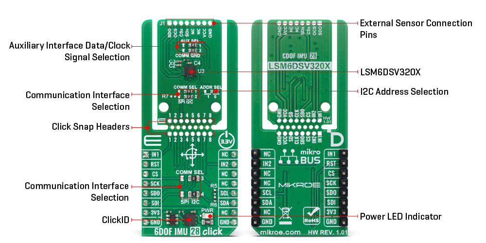
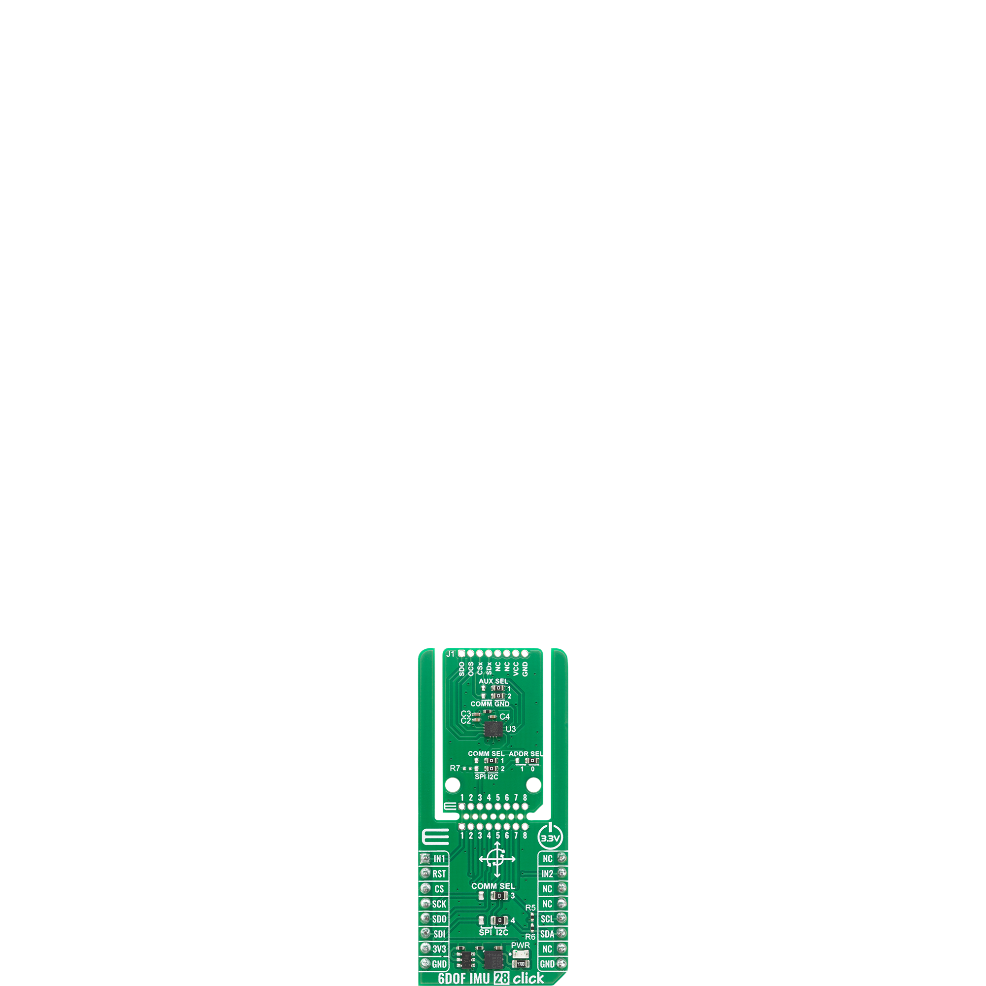
6DOF IMU 28 Click is based on the LSM6DSV320X, a 6-axis IMU that combines a low-g and high-g accelerometer with a digital gyroscope and advanced embedded intelligence from STMicroelectronics. This sensor integrates a 3-axis digital low-g accelerometer up to ±16g, a 3-axis digital high-g accelerometer up to ±320g, and a 3-axis digital gyroscope, forming a unique quad-channel architecture that processes acceleration and angular rate data on four separate channels: user interface, optical image stabilization (OIS), electronic image stabilization (EIS), and high-g accelerometer data – each with its own configuration, processing, and filtering. By embedding a dedicated high-g sensor channel, the LSM6DSV320X enables high-g shock and impact detection, making it ideal for car crash detection, concussion monitoring, and extreme sports applications. The LSM6DSV320X pushes edge computing further with its integrated finite state machine (FSM) and machine learning core (MLC), which allow configurable motion tracking, context awareness, and exportable AI features without relying on the host processor. Its adaptive self-configuration (ASC) feature dynamically reconfigures the device in real time based on detected motion patterns or decision tree outputs from the MLC, enhancing responsiveness and lowering power consumption for IoT and wearable designs. This combination of high-resolution sensing, embedded intelligence, and dedicated high-g detection opens up a broad range of applications, including IoT and connected devices, asset tracking, smartphones and handhelds, car
crash and shock detection, wearables, gesture recognition and motion tracking, augmented/virtual/mixed reality experiences, indoor navigation, vibration monitoring and compensation, as well as advanced camera stabilization for EIS and OIS. This Click board™ is designed in a unique format supporting the newly introduced MIKROE feature called "Click Snap." Unlike the standardized version of Click boards, this feature allows the main sensor/IC/module area to become movable by breaking the PCB, opening up many new possibilities for implementation. Thanks to the Snap feature, the LSM6DSV320X can operate autonomously by accessing its signals directly on the pins marked 1-8. Additionally, the Snap part includes a specified and fixed screw hole position, enabling users to secure the Snap board in their desired location. This board supports communication with the host MCU through either SPI (maximum clock frequency of 10MHz) or I2C (maximum clock frequency of 1MHz) interfaces, with I2C being the default option. The communication interface is selected by adjusting the COMM SEL jumper to the desired position. To enhance flexibility, particularly with the detachable Snap section of the Click Snap format, an additional COMM SEL jumpers are available. These jumpers functions the same as the COMM SEL, allowing for independent communication interface selection when the Snap section is used independently. To ensure proper functionality, all COMM jumpers must be set to the same interface. For those using the I2C interface, the board also provides an ADDR SEL jumper, enabling users to
configure the I2C address as needed for their specific application. The LSM6DSV320X enhances intelligent motion sensing with its dual event-detection interrupt pins (IN1 and IN2), enabling recognition of a wide range of movement and its J1 header, allowing the LSM6DSV320X to context-awareness events such as free-fall detection, 6D orientation, single and double-click actions, activity or inactivity status, stationary or motion detection, and wake-up triggers. This Click board™ also provides hardware flexibility through connect to external sensors and expand its functionality by adding features such as a sensor hub, auxiliary SPI, and more. In this configuration, the board supports the use of either auxiliary I3C or auxiliary SPI (3- or 4-wire) for transferring measured acceleration and angular rate data. Within the Snap section, an AUX SEL jumper is available to select the auxiliary interface data and clock signals, automatically routing the appropriate lines depending on whether the auxiliary SPI or I3C interface is active. The OCS pin on the J1 header serves as the auxiliary interface selector: when driven high, the pin places the auxiliary SPI in idle mode and enables the I3C interface, while when driven low, it activates auxiliary SPI communication and disables the I3C interface. This Click board™ can be operated only with a 3.3V logic voltage level. The board must perform appropriate logic voltage level conversion before using MCUs with different logic levels. It also comes equipped with a library containing functions and example code that can be used as a reference for further development.
Features overview
Development board
Nucleo 32 with STM32F031K6 MCU board provides an affordable and flexible platform for experimenting with STM32 microcontrollers in 32-pin packages. Featuring Arduino™ Nano connectivity, it allows easy expansion with specialized shields, while being mbed-enabled for seamless integration with online resources. The
board includes an on-board ST-LINK/V2-1 debugger/programmer, supporting USB reenumeration with three interfaces: Virtual Com port, mass storage, and debug port. It offers a flexible power supply through either USB VBUS or an external source. Additionally, it includes three LEDs (LD1 for USB communication, LD2 for power,
and LD3 as a user LED) and a reset push button. The STM32 Nucleo-32 board is supported by various Integrated Development Environments (IDEs) such as IAR™, Keil®, and GCC-based IDEs like AC6 SW4STM32, making it a versatile tool for developers.

Microcontroller Overview
MCU Card / MCU

Architecture
ARM Cortex-M0
MCU Memory (KB)
32
Silicon Vendor
STMicroelectronics
Pin count
32
RAM (Bytes)
4096
You complete me!
Accessories
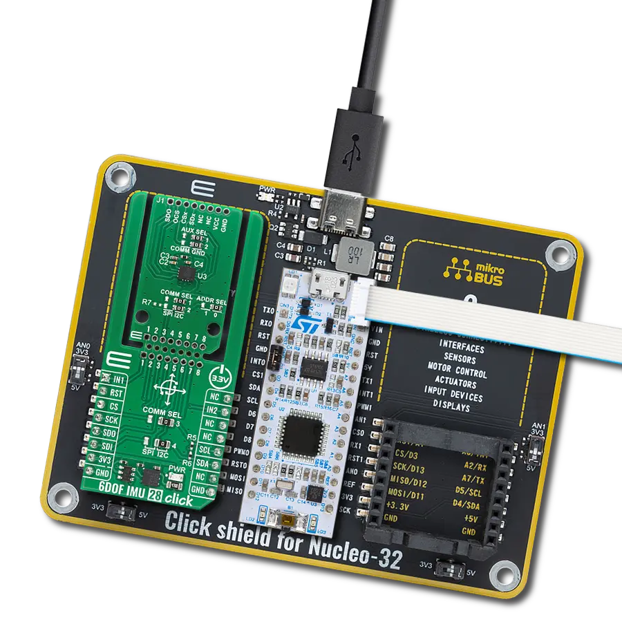
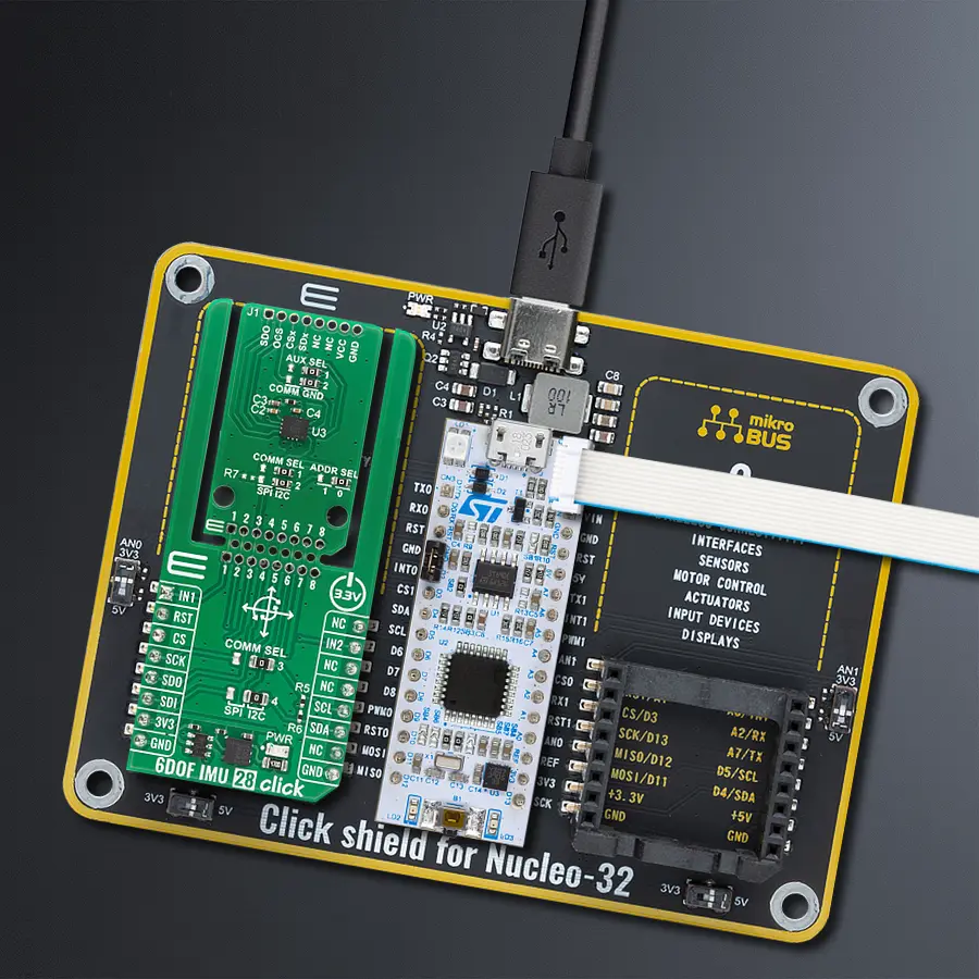
Click Shield for Nucleo-32 is the perfect way to expand your development board's functionalities with STM32 Nucleo-32 pinout. The Click Shield for Nucleo-32 provides two mikroBUS™ sockets to add any functionality from our ever-growing range of Click boards™. We are fully stocked with everything, from sensors and WiFi transceivers to motor control and audio amplifiers. The Click Shield for Nucleo-32 is compatible with the STM32 Nucleo-32 board, providing an affordable and flexible way for users to try out new ideas and quickly create prototypes with any STM32 microcontrollers, choosing from the various combinations of performance, power consumption, and features. The STM32 Nucleo-32 boards do not require any separate probe as they integrate the ST-LINK/V2-1 debugger/programmer and come with the STM32 comprehensive software HAL library and various packaged software examples. This development platform provides users with an effortless and common way to combine the STM32 Nucleo-32 footprint compatible board with their favorite Click boards™ in their upcoming projects.

Used MCU Pins
mikroBUS™ mapper
Take a closer look
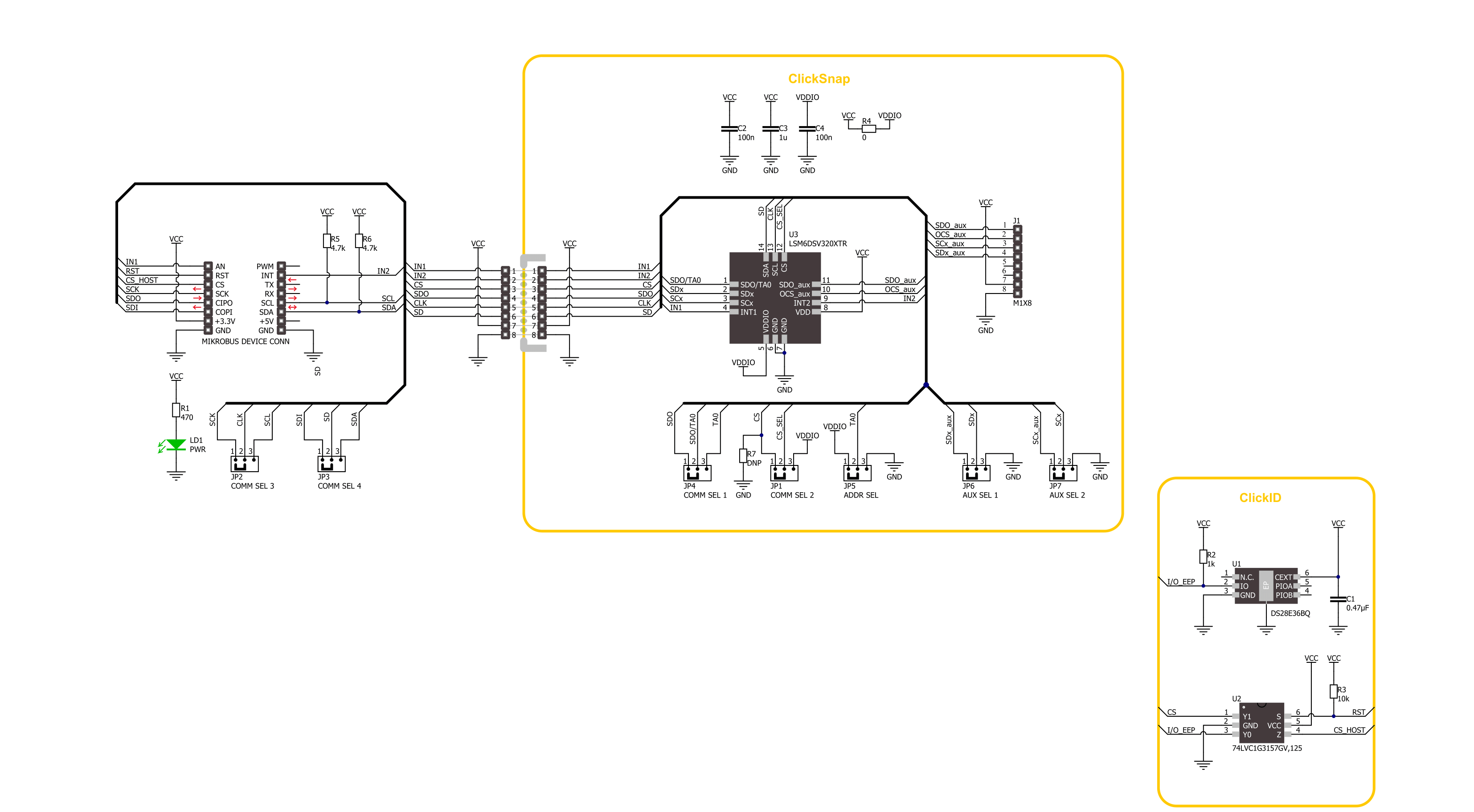
Click board™ Schematic
Step by step
Project assembly

Start by selecting your development board and Click board™. Begin with the Nucleo 32 with STM32F031K6 MCU as your development board.


Software Support
Library Description
6DOF IMU 28 Click demo application is developed using the NECTO Studio, ensuring compatibility with mikroSDK's open-source libraries and tools. Designed for plug-and-play implementation and testing, the demo is fully compatible with all development, starter, and mikromedia boards featuring a mikroBUS™ socket.
Example Description
This example demonstrates the use of 6DOF IMU 28 Click board by reading and displaying the accelerometer and gyroscope data (X, Y, and Z axis) as well as a temperature measurement in degrees Celsius.
Key functions:
c6dofimu28_cfg_setup- This function initializes Click configuration structure to initial values.c6dofimu28_init- This function initializes all necessary pins and peripherals used for this Click board.c6dofimu28_default_cfg- This function executes a default configuration of 6DOF IMU 28 Click board.c6dofimu28_get_int1_pin- This function returns the interrupt 1 pin logic state.c6dofimu28_get_data- This function reads the accelerometer, gyroscope, and temperature measurement data.
Application Init
Initializes the driver and performs the Click default configuration.
Application Task
Waits for a data ready indication and then reads the accelerometer, gyroscope, and temperature measurements. The results are displayed on the USB UART at 7.5 Hz output data rate.
Open Source
Code example
The complete application code and a ready-to-use project are available through the NECTO Studio Package Manager for direct installation in the NECTO Studio. The application code can also be found on the MIKROE GitHub account.
/*!
 * @file main.c
 * @brief 6DOF IMU 28 Click example
 *
 * # Description
 * This example demonstrates the use of 6DOF IMU 28 Click board by reading and displaying
 * the accelerometer and gyroscope data (X, Y, and Z axis) as well as a temperature measurement
 * in degrees Celsius.
 *
 * The demo application is composed of two sections :
 *
 * ## Application Init
 * Initializes the driver and performs the Click default configuration.
 *
 * ## Application Task
 * Waits for a data ready indication and then reads the accelerometer, gyroscope, and temperature
 * measurements. The results are displayed on the USB UART at 7.5 Hz output data rate.
 *
 * @author Stefan Filipovic
 *
 */

#include "board.h"
#include "log.h"
#include "c6dofimu28.h"

static c6dofimu28_t c6dofimu28;
static log_t logger;

void application_init ( void )
{
    log_cfg_t log_cfg;  /**< Logger config object. */
    c6dofimu28_cfg_t c6dofimu28_cfg;  /**< Click config object. */

    /**
     * Logger initialization.
     * Default baud rate: 115200
     * Default log level: LOG_LEVEL_DEBUG
     * @note If USB_UART_RX and USB_UART_TX
     * are defined as HAL_PIN_NC, you will
     * need to define them manually for log to work.
     * See @b LOG_MAP_USB_UART macro definition for detailed explanation.
     */
    LOG_MAP_USB_UART( log_cfg );
    log_init( &logger, &log_cfg );
    log_info( &logger, " Application Init " );

    // Click initialization.
    c6dofimu28_cfg_setup( &c6dofimu28_cfg );
    C6DOFIMU28_MAP_MIKROBUS( c6dofimu28_cfg, MIKROBUS_1 );
    err_t init_flag = c6dofimu28_init( &c6dofimu28, &c6dofimu28_cfg );
    if ( ( I2C_MASTER_ERROR == init_flag ) || ( SPI_MASTER_ERROR == init_flag ) )
    {
        log_error( &logger, " Communication init." );
        for ( ; ; );
    }

    if ( C6DOFIMU28_ERROR == c6dofimu28_default_cfg ( &c6dofimu28 ) )
    {
        log_error( &logger, " Default configuration." );
        for ( ; ; );
    }

    log_info( &logger, " Application Task " );
}

void application_task ( void )
{
    c6dofimu28_data_t meas_data;
    if ( c6dofimu28_get_int1_pin ( &c6dofimu28 ) )
    {
        if ( C6DOFIMU28_OK == c6dofimu28_get_data ( &c6dofimu28, &meas_data ) )
        {
            log_printf( &logger, " Accel X: %.3f g\r\n", meas_data.accel.x );
            log_printf( &logger, " Accel Y: %.3f g\r\n", meas_data.accel.y );
            log_printf( &logger, " Accel Z: %.3f g\r\n", meas_data.accel.z );
            log_printf( &logger, " Gyro X: %.1f dps\r\n", meas_data.gyro.x );
            log_printf( &logger, " Gyro Y: %.1f dps\r\n", meas_data.gyro.y );
            log_printf( &logger, " Gyro Z: %.1f dps\r\n", meas_data.gyro.z );
            log_printf( &logger, " Temperature: %.2f degC\r\n\n", meas_data.temperature );
        }
    }
}

int main ( void )
{
    /* Do not remove this line or clock might not be set correctly. */
    #ifdef PREINIT_SUPPORTED
    preinit();
    #endif

    application_init( );

    for ( ; ; )
    {
        application_task( );
    }

    return 0;
}

// ------------------------------------------------------------------------ END
Additional Support
Resources
Category:Motion


