Achieve biopotential signal detection alongisde motion tracking with ST1VAFE6AX and PIC32MX470F512H
6-axis IMU solution with biosensor with vAFE (vertical analog front-end) for biopotential signal detection
Published Dec 12, 2024
Click board™
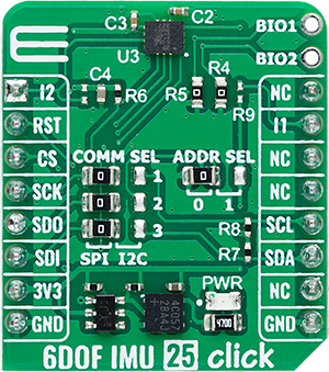
6DOF IMU 25 Click
Dev. board
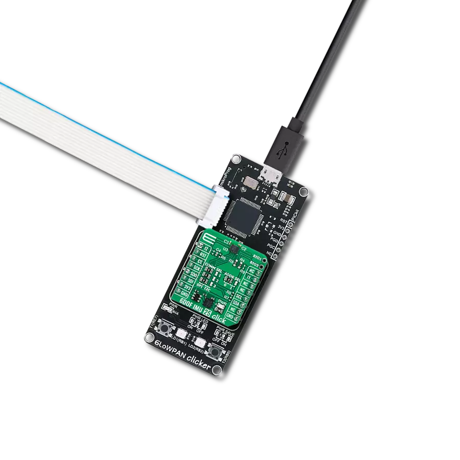
6LoWPAN clicker
Compiler
NECTO Studio
MCU
PIC32MX470F512H
Combine biopotential sensing and motion tracking perfect for ECG, heart rate monitoring, and wearable activity tracking
A
A
Hardware Overview
How does it work?
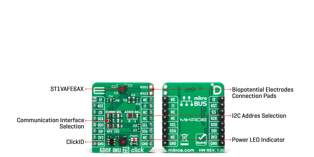
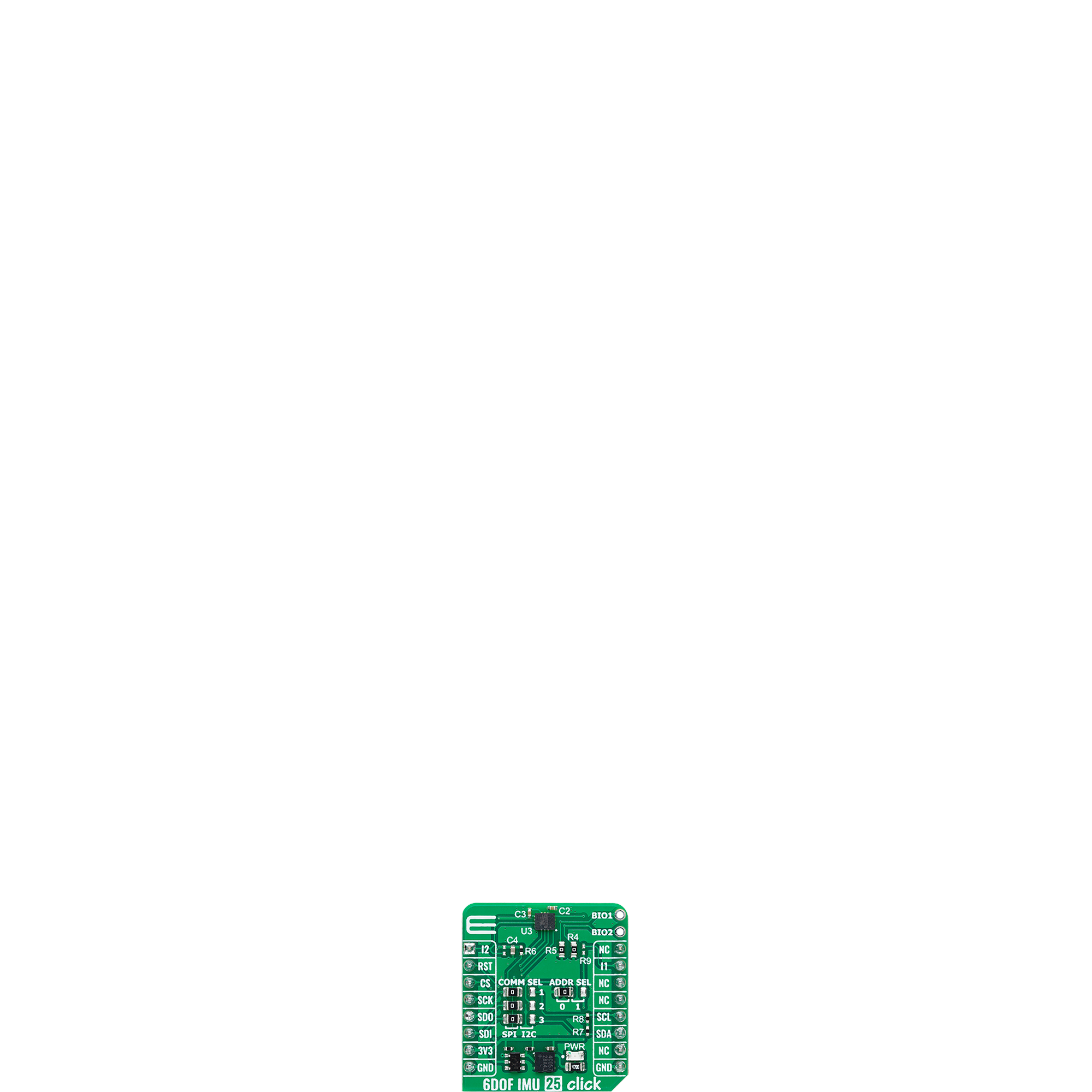
6DOF IMU 25 Click is based on the ST1VAFE6AX, an advanced biosensor from STMicroelectronics that integrates a vertical analog front-end (vAFE) for biopotential signal detection with a high-performance 6-axis inertial measurement unit (IMU). This dual-function device combines a 3-axis digital accelerometer (with selectable full-scale ranges of ±2/±4/±8/±16 g) and a 3-axis digital gyroscope (offering ranges of ±125/±250/±500/±1000/±2000/±4000 dps) for precise motion tracking. The sensor also includes state-of-the-art features like a finite state machine (FSM), sensor fusion low power (SFLP), adaptive self-configuration (ASC), and a machine learning core (MLC) with AI-capable filters, ensuring versatile performance across a range of applications. The ST1VAFE6AX's innovative vAFE channel is optimized for low-power operation and supports configurable input impedance, enabling easy acquisition of biopotential signals from BIO pads alongside motion data. This synchronized integration ensures context-aware analysis directly at the sensor level, minimizing latency and power
consumption. By leveraging its embedded features like FSM and MLC, the sensor enables standalone processing, reducing the workload on the microcontroller and supporting efficient edge computing. The result is a compact, versatile solution capable of performing advanced signal processing and machine learning tasks in resource-constrained environments. A built-in 4.5KB FIFO buffer with compression and dynamic data allocation further enhances system power efficiency, allowing for optimized data handling and reduced processor intervention. The combined capabilities of the vAFE and IMU make 6DOF IMU 25 Click ideal for applications requiring precise biopotential signal monitoring and motion analysis such as heart rate and pulse monitoring, electrocardiograms (ECG), activity tracking, and well-being in digital healthcare, as well as wearable and portable devices. Biopotential and motion data are accessed through the I2C or SPI interface, with a maximum frequency of 1MHz for I2C and 10MHz for SPI communication. The selection is made by positioning SMD jumpers labeled COMM SEL
appropriately. Note that all the jumpers' positions must be on the same side, or the Click board™ may become unresponsive. While the I2C interface is selected, the ST1VAFE6AX allows the least significant bit (LSB) of its I2C address to be chosen using the SMD jumper labeled ADDR SEL. This board also possesses two interrupts, I1 and I2, routed to, where, by default, the INT and AN pins stand on the mikroBUS™ socket, entirely programmed by the user through a serial interface. The event-detection interrupts enable efficient and reliable motion tracking and context awareness, implementing hardware recognition of free-fall events, 6D orientation, click and double-click sensing, activity or inactivity, stationary/motion detection, and wake-up events. This Click board™ can be operated only with a 3.3V logic voltage level. The board must perform appropriate logic voltage level conversion before using MCUs with different logic levels. It also comes equipped with a library containing functions and example code that can be used as a reference for further development.
Features overview
Development board
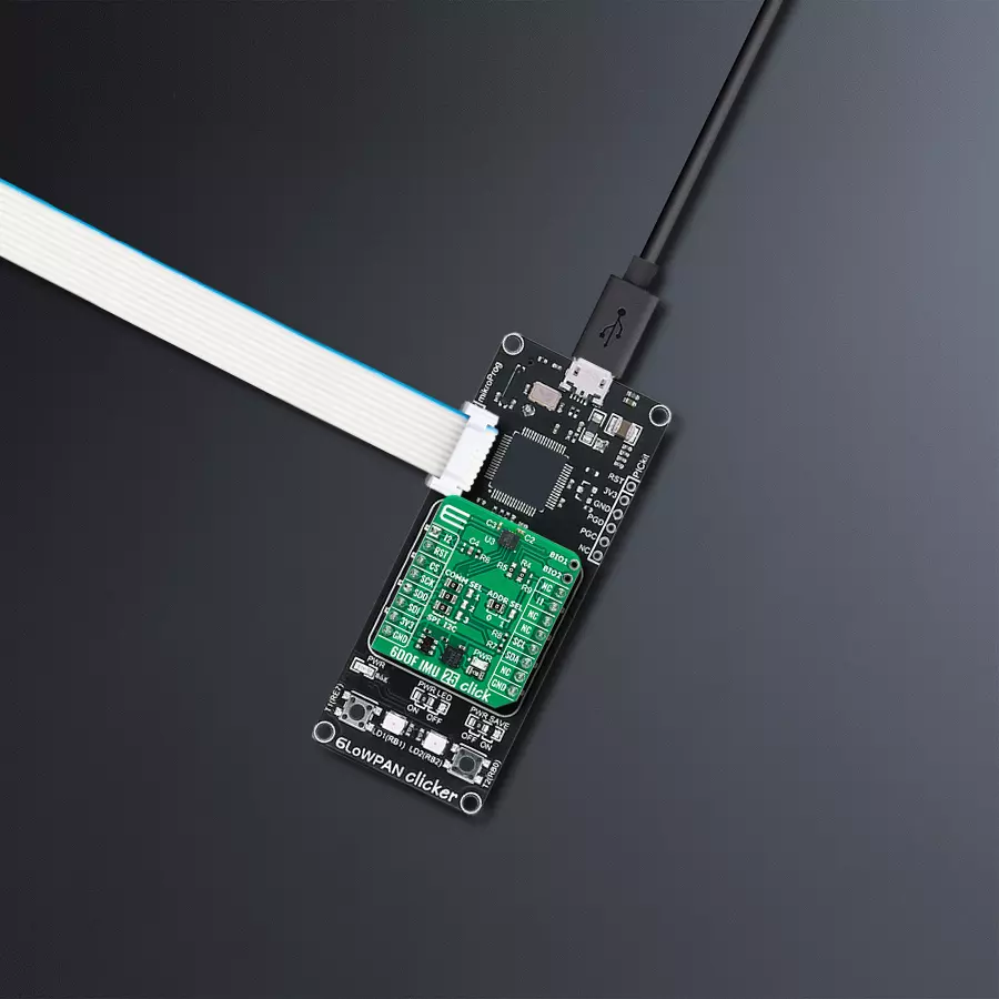
6LoWPAN Clicker is a compact starter development board that brings the flexibility of add-on Click boards™ to your favorite microcontroller, making it a perfect starter kit for implementing your ideas. It comes with an onboard 32-bit PIC microcontroller, the PIC32MX470F512H from Microchip, a USB connector, LED indicators, buttons, a mikroProg connector, and a header for interfacing with external electronics. Along with this microcontroller, the board also contains a 2.4GHz ISM band transceiver, allowing you to add wireless communication to your target application. Its compact design provides a fluid and immersive working experience, allowing access anywhere
and under any circumstances. Each part of the 6LoWPAN Clicker development kit contains the components necessary for the most efficient operation of the same board. In addition to the possibility of choosing the 6LoWPAN Clicker programming method, using USB HID mikroBootloader, or through an external mikroProg connector for PIC, dsPIC, or PIC32 programmer, the Clicker board also includes a clean and regulated power supply module for the development kit. The USB Micro-B connection can provide up to 500mA of current for the Clicker board, which is more than enough to operate all onboard and additional modules, or it can power
over two standard AA batteries. All communication methods that mikroBUS™ itself supports are on this board, including the well-established mikroBUS™ socket, reset button, and several buttons and LED indicators. 6LoWPAN Clicker is an integral part of the Mikroe ecosystem, allowing you to create a new application in minutes. Natively supported by Mikroe software tools, it covers many aspects of prototyping thanks to a considerable number of different Click boards™ (over a thousand boards), the number of which is growing every day.

Microcontroller Overview
MCU Card / MCU

Architecture
PIC32
MCU Memory (KB)
512
Silicon Vendor
Microchip
Pin count
64
RAM (Bytes)
131072
Used MCU Pins
mikroBUS™ mapper
Take a closer look
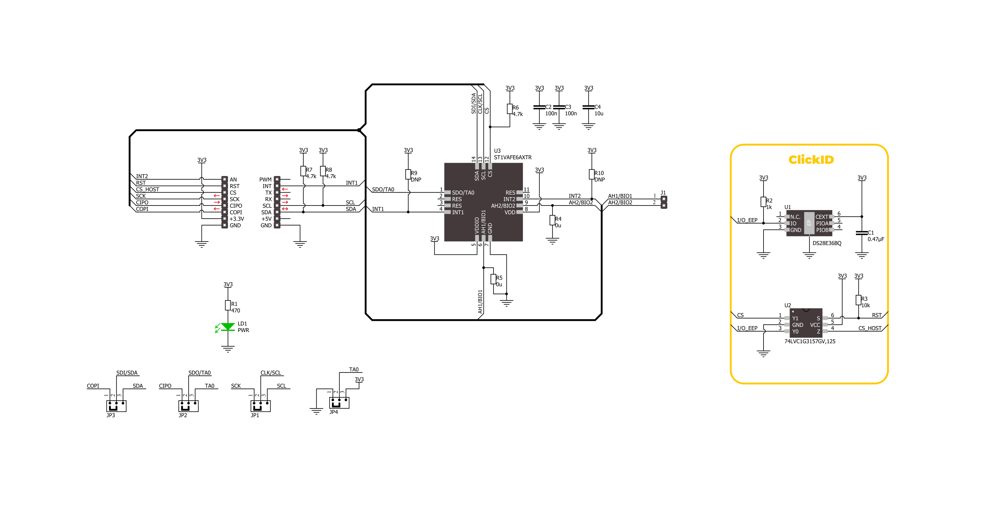
Click board™ Schematic
Step by step
Project assembly

Start by selecting your development board and Click board™. Begin with the 6LoWPAN clicker as your development board.


Software Support
Library Description
This library contains API for 6DOF IMU 25 Click driver.
Key functions:
c6dofimu25_get_int1_pin- This function returns the interrupt 1 pin logic state.c6dofimu25_get_data- This function reads the accelerometer, gyroscope, and temperature measurement data.c6dofimu25_set_accel_fsr- This function sets the accel measurement full scale range.
Open Source
Code example
The complete application code and a ready-to-use project are available through the NECTO Studio Package Manager for direct installation in the NECTO Studio. The application code can also be found on the MIKROE GitHub account.
/*!
 * @file main.c
 * @brief 6DOF IMU 25 Click example
 *
 * # Description
 * This example demonstrates the use of 6DOF IMU 25 Click board by reading and displaying
 * the accelerometer and gyroscope data (X, Y, and Z axis) as well as a temperature measurement
 * in degrees Celsius.
 *
 * The demo application is composed of two sections :
 *
 * ## Application Init
 * Initializes the driver and performs the Click default configuration.
 *
 * ## Application Task
 * Waits for a data ready indication and then reads the accelerometer, gyroscope, and temperature
 * measurements. The results are displayed on the USB UART at 7.5 Hz output data rate.
 *
 * @author Stefan Filipovic
 *
 */

#include "board.h"
#include "log.h"
#include "c6dofimu25.h"

static c6dofimu25_t c6dofimu25;
static log_t logger;

void application_init ( void )
{
    log_cfg_t log_cfg;  /**< Logger config object. */
    c6dofimu25_cfg_t c6dofimu25_cfg;  /**< Click config object. */

    /**
     * Logger initialization.
     * Default baud rate: 115200
     * Default log level: LOG_LEVEL_DEBUG
     * @note If USB_UART_RX and USB_UART_TX
     * are defined as HAL_PIN_NC, you will
     * need to define them manually for log to work.
     * See @b LOG_MAP_USB_UART macro definition for detailed explanation.
     */
    LOG_MAP_USB_UART( log_cfg );
    log_init( &logger, &log_cfg );
    log_info( &logger, " Application Init " );

    // Click initialization.
    c6dofimu25_cfg_setup( &c6dofimu25_cfg );
    C6DOFIMU25_MAP_MIKROBUS( c6dofimu25_cfg, MIKROBUS_1 );
    err_t init_flag = c6dofimu25_init( &c6dofimu25, &c6dofimu25_cfg );
    if ( ( I2C_MASTER_ERROR == init_flag ) || ( SPI_MASTER_ERROR == init_flag ) )
    {
        log_error( &logger, " Communication init." );
        for ( ; ; );
    }

    if ( C6DOFIMU25_ERROR == c6dofimu25_default_cfg ( &c6dofimu25 ) )
    {
        log_error( &logger, " Default configuration." );
        for ( ; ; );
    }

    log_info( &logger, " Application Task " );
}

void application_task ( void )
{
    c6dofimu25_data_t meas_data;
    if ( c6dofimu25_get_int1_pin ( &c6dofimu25 ) )
    {
        if ( C6DOFIMU25_OK == c6dofimu25_get_data ( &c6dofimu25, &meas_data ) )
        {
            log_printf( &logger, " Accel X: %.3f g\r\n", meas_data.accel.x );
            log_printf( &logger, " Accel Y: %.3f g\r\n", meas_data.accel.y );
            log_printf( &logger, " Accel Z: %.3f g\r\n", meas_data.accel.z );
            log_printf( &logger, " Gyro X: %.1f dps\r\n", meas_data.gyro.x );
            log_printf( &logger, " Gyro Y: %.1f dps\r\n", meas_data.gyro.y );
            log_printf( &logger, " Gyro Z: %.1f dps\r\n", meas_data.gyro.z );
            log_printf( &logger, " Temperature: %.2f degC\r\n\n", meas_data.temperature );
        }
    }
}

int main ( void )
{
    /* Do not remove this line or clock might not be set correctly. */
    #ifdef PREINIT_SUPPORTED
    preinit();
    #endif

    application_init( );

    for ( ; ; )
    {
        application_task( );
    }

    return 0;
}

// ------------------------------------------------------------------------ END
Additional Support
Resources
Category:Motion


