Harness the full potential of proximity detection with VCNL36687S and PIC18LF26K40
Proximity sensing: Your personal digital security

Published Nov 01, 2023
Click board™
Proximity 8 Click
Dev. board
EasyPIC v8
Compiler
NECTO Studio
MCU
PIC18LF26K40
Explore the uncharted territories of proximity detection and witness how it's shaping the technological landscape
A
A
Hardware Overview
How does it work?
Proximity 8 Click is based on the VCNL36687S, a proximity sensor with VCSEL in a single package, with the I2C Interface from Vishay. This is a proximity sensor aimed towards portable, mobile and IoT applications, where close proximity detection is required. A good example might be a display activation in the close proximity of an operator. The sensor itself has an advanced analog and digital frontend circuits, which make it easy working with the sensor: it can be set to trigger a PS detection by a single operation over the I2C. The rest of the time, it will stay in the standby mode, saving the power that way. The VCNL36687S features a 12-bit ADC, therefore the output data is in 12-bit format. There are two registers that are used to hold the output result. Besides the four Most Significant Bits (MSBs), the PS data output high-byte register contains another bit that indicates that the device entered the sunlight protection mode. The operation of the VCNL36687S can be configured by writing to a set of CONFIG registers. There are four config registers, which are used to set the PS sampling
period, interrupt persistence value, smart persistence, interrupt, operating mode, etc. The comprehensive list of all the registers and their function is given within the VCNL36687S datasheet. However, Proximity 8 click supports a mikroSDK compatible library, which contains a set of functions used to simplify and accelerate the development. There are two pairs of threshold registers, used to trigger an interrupt when the measurement exceeds their values. These registers contain two 12-bit values, which represent the boundaries of the detection window. Each time one of these values is exceeded, an interrupt will be generated, and the INT pin will be asserted to a LOW logic level. The interrupt flag bit indicates the condition that caused an interrupt. The interrupt persistence can be set, preventing false triggering: the INT pin will be asserted only after a number of consecutive measurements that exceed either of the threshold values. This pin is routed to the mikroBUS™ INT pin, and it is normally pulled up by a resistor. Another feature of the VCNL36687S sensor is the Logic Output mode:
close proximity of an object will trigger an interrupt (a logic LOW level on the INT pin). When the object moves away, the INT pin will be de-asserted (a logic HIGH level on the INT pin). The difference between this mode and the other modes is that the user does not have to read the status bit to clear the interrupt and de-assert the INT pin. It will be controlled automatically by the low/high threshold values. To improve the reliability of the detection, the VCNL36687S employs a smart cancelation scheme. It uses the value stored within the register to subtract it from the output measurement, reducing the crosstalk phenomenon. A sunlight mode allows the device to be used even when exposed to sunlight. The VCNL36687S is operated by 1.8V, therefore a voltage regulator IC had to be used. The logic section of the VCNL36687S allows it to be operated at 3.3V directly, so no logic level translation is required if the Click board™ is used with MCUs that use 3.3V logic levels. However, if operated by an MCU that uses 5V for logic levels, a proper logic level voltage translation is required.


Features overview
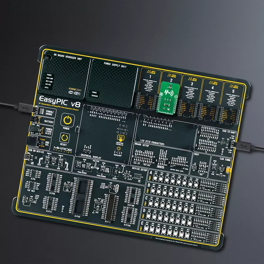
Development board
EasyPIC v8 is a development board specially designed for the needs of rapid development of embedded applications. It supports many high pin count 8-bit PIC microcontrollers from Microchip, regardless of their number of pins, and a broad set of unique functions, such as the first-ever embedded debugger/programmer. The development board is well organized and designed so that the end-user has all the necessary elements, such as switches, buttons, indicators, connectors, and others, in one place. Thanks to innovative manufacturing technology, EasyPIC v8 provides a fluid and immersive working experience, allowing access anywhere and under any
circumstances at any time. Each part of the EasyPIC v8 development board contains the components necessary for the most efficient operation of the same board. In addition to the advanced integrated CODEGRIP programmer/debugger module, which offers many valuable programming/debugging options and seamless integration with the Mikroe software environment, the board also includes a clean and regulated power supply module for the development board. It can use a wide range of external power sources, including a battery, an external 12V power supply, and a power source via the USB Type-C (USB-C) connector.
Communication options such as USB-UART, USB DEVICE, and CAN are also included, including the well-established mikroBUS™ standard, two display options (graphical and character-based LCD), and several different DIP sockets. These sockets cover a wide range of 8-bit PIC MCUs, from the smallest PIC MCU devices with only eight up to forty pins. EasyPIC v8 is an integral part of the Mikroe ecosystem for rapid development. Natively supported by Mikroe software tools, it covers many aspects of prototyping and development thanks to a considerable number of different Click boards™ (over a thousand boards), the number of which is growing every day.

Microcontroller Overview
MCU Card / MCU
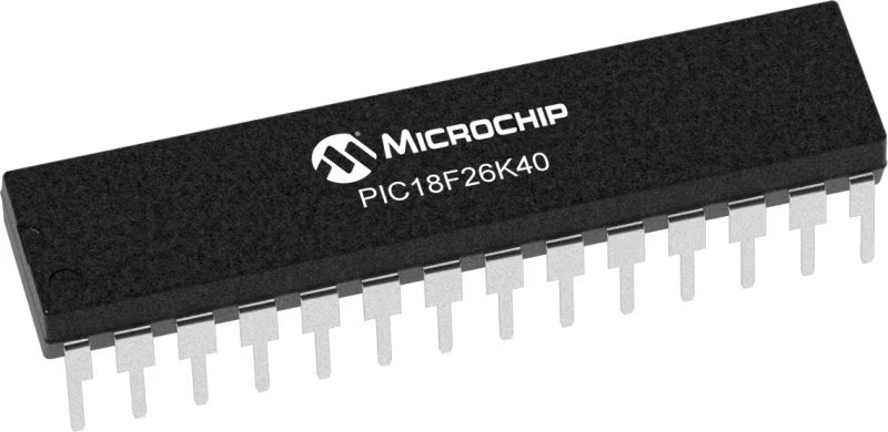
Architecture
PIC
MCU Memory (KB)
64
Silicon Vendor
Microchip
Pin count
28
RAM (Bytes)
3728
Used MCU Pins
mikroBUS™ mapper
Take a closer look
Click board™ Schematic

Step by step
Project assembly

Start by selecting your development board and Click board™. Begin with the EasyPIC v8 as your development board.


Software Support
Library Description
This library contains API for Proximity 8 Click driver.
Key functions:
proximity8_generic_read- This function reads data from the desired registerproximity8_generic_write- This function writes data to the desired registerproximity8_get_interrupt_state- This function returns Interrupt state
Open Source
Code example
The complete application code and a ready-to-use project are available through the NECTO Studio Package Manager for direct installation in the NECTO Studio. The application code can also be found on the MIKROE GitHub account.
/*!
 * \file
 * \brief Proximity8 Click example
 *
 * # Description
 * This application enables usage of the proximity sensor
 *
 * The demo application is composed of two sections :
 *
 * ## Application Init
 * Initialization Driver init, test comunication and configuration chip for measurement
 *
 * ## Application Task
 * Reads Proximity data and this data logs to the USBUART every 1500ms.
 *
 * *note:*
 * The reading value and proximity of the data depend on the configuration.
 *
 * \author MikroE Team
 *
 */
// ------------------------------------------------------------------- INCLUDES

#include "board.h"
#include "log.h"
#include "proximity8.h"

// ------------------------------------------------------------------ VARIABLES

static proximity8_t proximity8;
static log_t logger;

// ------------------------------------------------------ APPLICATION FUNCTIONS

void application_init ( void )
{
    log_cfg_t log_cfg;
    proximity8_cfg_t cfg;
    uint16_t tmp;
    uint16_t w_temp;

    /**
     * Logger initialization.
     * Default baud rate: 115200
     * Default log level: LOG_LEVEL_DEBUG
     * @note If USB_UART_RX and USB_UART_TX
     * are defined as HAL_PIN_NC, you will
     * need to define them manually for log to work.
     * See @b LOG_MAP_USB_UART macro definition for detailed explanation.
     */
    LOG_MAP_USB_UART( log_cfg );
    log_init( &logger, &log_cfg );
    log_info( &logger, "---- Application Init ----" );

    //  Click initialization.

    proximity8_cfg_setup( &cfg );
    PROXIMITY8_MAP_MIKROBUS( cfg, MIKROBUS_1 );
    proximity8_init( &proximity8, &cfg );

    //Test Communication

    proximity8_generic_read( &proximity8, PROXIMITY8_REG_DEVICE_ID, &tmp );

    if ( tmp == PROXIMITY8_DEVICE_ID )
    {
        log_printf( &logger, "---- Comunication OK!!! ----\r\n" );
    }
    else
    {
        log_printf( &logger, "---- Comunication ERROR!!! ----\r\n" );
        for ( ; ; );
    }

    proximity8_default_cfg( &proximity8 );

    log_printf( &logger, "---- Start measurement ----\r\n" );
}

void application_task ( void )
{
   uint16_t proximity;

   proximity8_generic_read( &proximity8, PROXIMITY8_REG_PROX_DATA, &proximity );
   proximity = ( proximity & 0x7FFF );

   log_printf( &logger, " Proximity data: %d\r\n", proximity );

   log_printf( &logger, "-------------------------\r\n" );
   Delay_ms ( 1000 );
   Delay_ms ( 500 );
}

int main ( void )
{
    /* Do not remove this line or clock might not be set correctly. */
    #ifdef PREINIT_SUPPORTED
    preinit();
    #endif

    application_init( );

    for ( ; ; )
    {
        application_task( );
    }

    return 0;
}


// ------------------------------------------------------------------------ END


