Gain real-time insights into the behavior of electrical currents using ACS70331 and TM4C129ENCPDT
Your path to reliable ampere insights
Published Aug 12, 2023
Click board™
Current 4 Click
Dev. board
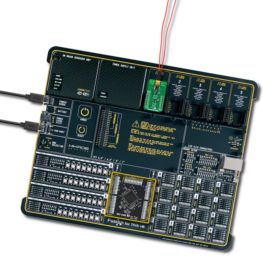
Fusion for Tiva v8
Compiler
NECTO Studio
MCU
TM4C129ENCPDT
Achieve operational excellence by utilizing our current measurement solution to track current variations, enabling you to make data-driven decisions for improved efficiency and reduced downtime
A
A
Hardware Overview
How does it work?
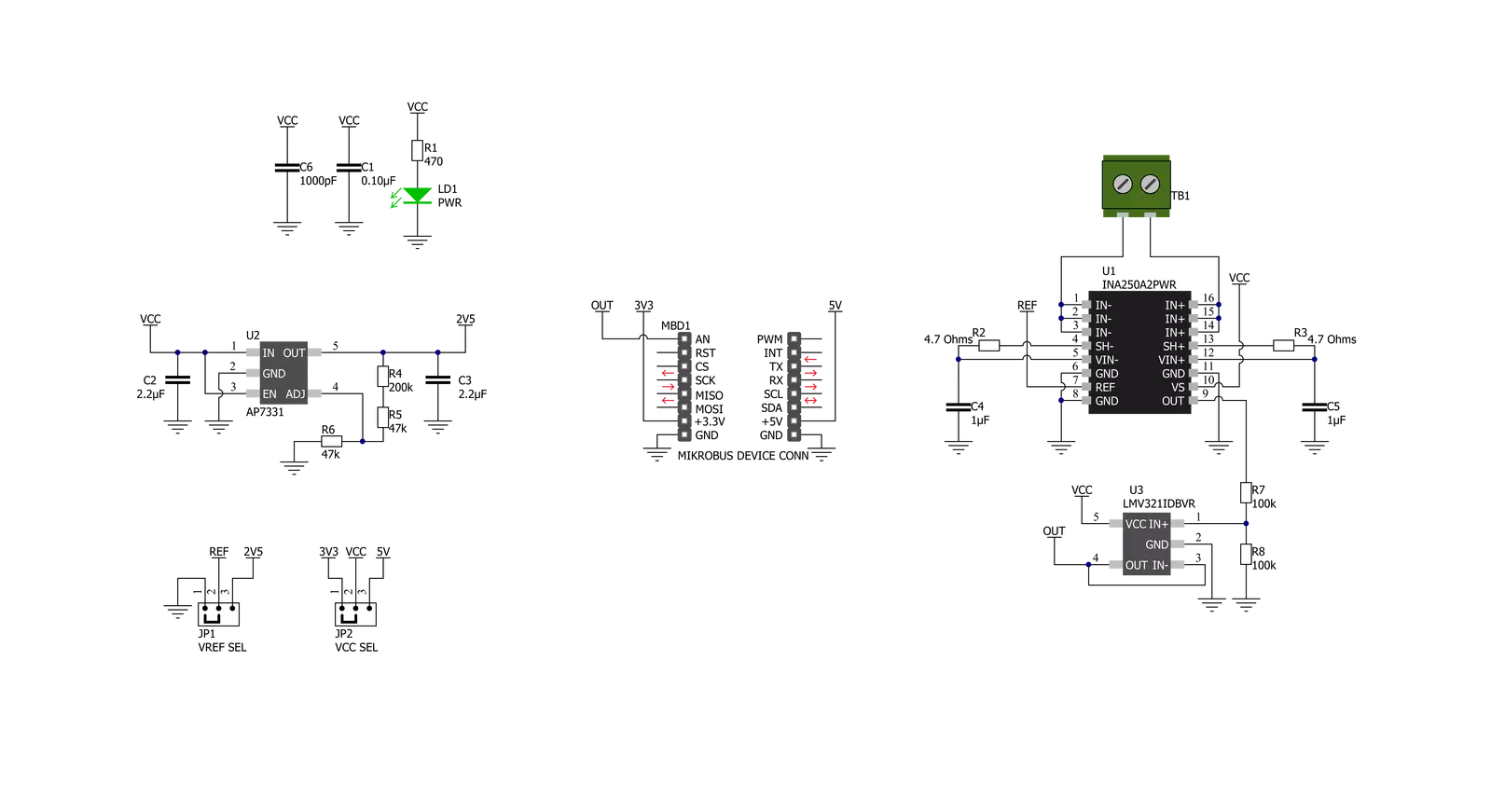
Current 4 Click is based on the INA250, a current-sense amplifier with a high-precision, low-drift shunt resistor, which can deliver highly accurate measurements over a wide temperature range from Texas Instruments. The INA250 measures the voltage developed across the internal current-sensing resistor when current passes through it. The integrated 2mΩ shunt resistor offers 0.1% tolerance and a low drift of 15pmm/°C, enabling the higher performance of the end equipment. This amplifier allows for high-accuracy current measurements at common-mode voltages and offers a maximum error of 0.84% over a wide temperature range. Current 4 Click communicates with MCU using only one pin routed on the AN pin of the mikroBUS™ socket. The output analog
signal from INA250 is forwarded to the input of the operational amplifier, the LMV321 low-voltage rail-to-rail OpAmp from Texas Instruments, representing the most cost-effective solution for applications where low voltage operation is needed. The output of the LMV321 OpAmp has a stable unity gain, acting as a buffer so that the host MCU can sample the output voltage of the INA250 via the AN pin of the mikroBUS™ socket. The INA250 can be configured to measure both unidirectional and bidirectional currents through the reference voltage level. For unidirectional operation, the reference pin should be tied to the ground. When the current increases, the output signal increases upwards from this reference voltage (or ground in this case). For bidirectional
currents, an external voltage source can be used as the reference voltage; in this case, a low dropout linear regulator AP7331 from Diodes Incorporated provides the 2.5V reference supply voltage for the INA250. The reference voltage level can be selected by positioning the SMD jumper labeled VREF SEL to an appropriate position choosing between 2.5V provided by AP7331 or GND. This Click board™ can operate with either 3.3V or 5V logic voltage levels selected via the VCC SEL jumper. This way, both 3.3V and 5V capable MCUs can use the communication lines properly. Also, this Click board™ comes equipped with a library containing easy-to-use functions and an example code that can be used, as a reference, for further development.


Features overview
Development board
Fusion for TIVA v8 is a development board specially designed for the needs of rapid development of embedded applications. It supports a wide range of microcontrollers, such as different 32-bit ARM® Cortex®-M based MCUs from Texas Instruments, regardless of their number of pins, and a broad set of unique functions, such as the first-ever embedded debugger/programmer over a WiFi network. The development board is well organized and designed so that the end-user has all the necessary elements, such as switches, buttons, indicators, connectors, and others, in one place. Thanks to innovative manufacturing technology, Fusion for TIVA v8 provides a fluid and immersive working experience, allowing access
anywhere and under any circumstances at any time. Each part of the Fusion for TIVA v8 development board contains the components necessary for the most efficient operation of the same board. An advanced integrated CODEGRIP programmer/debugger module offers many valuable programming/debugging options, including support for JTAG, SWD, and SWO Trace (Single Wire Output)), and seamless integration with the Mikroe software environment. Besides, it also includes a clean and regulated power supply module for the development board. It can use a wide range of external power sources, including a battery, an external 12V power supply, and a power source via the USB Type-C (USB-C) connector.
Communication options such as USB-UART, USB HOST/DEVICE, CAN (on the MCU card, if supported), and Ethernet is also included. In addition, it also has the well-established mikroBUS™ standard, a standardized socket for the MCU card (SiBRAIN standard), and two display options for the TFT board line of products and character-based LCD. Fusion for TIVA v8 is an integral part of the Mikroe ecosystem for rapid development. Natively supported by Mikroe software tools, it covers many aspects of prototyping and development thanks to a considerable number of different Click boards™ (over a thousand boards), the number of which is growing every day.

Microcontroller Overview
MCU Card / MCU

Type
8th Generation
Architecture
ARM Cortex-M4
MCU Memory (KB)
1024
Silicon Vendor
Texas Instruments
Pin count
128
RAM (Bytes)
262144
Used MCU Pins
mikroBUS™ mapper
Take a closer look
Click board™ Schematic
Step by step
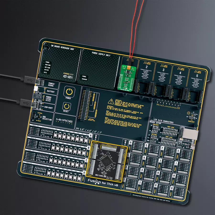
Project assembly

Start by selecting your development board and Click board™. Begin with the Fusion for Tiva v8 as your development board.


Software Support
Library Description
This library contains API for Current 4 Click driver.
Key functions:
current4_read_load_current- Read load currentcurrent4_read_an_pin_voltage- Read AN pin voltage level functioncurrent4_read_an_pin_value- Read AN pin value function.
Open Source
Code example
The complete application code and a ready-to-use project are available through the NECTO Studio Package Manager for direct installation in the NECTO Studio. The application code can also be found on the MIKROE GitHub account.
/*!
* @file main.c
* @brief Current 4 Click Example.
*
* # Description
* This example showcases the ability of the Current 4 Click board.
* It configures Host MCU for communication and reads the voltage
* of AN pin and calculates current on load output.
*
* The demo application is composed of two sections :
*
* ## Application Init
* Initialization of the communication modules(ADC and UART).
*
* ## Application Task
* In span on 500ms reads voltage and calculates the current on load.
*
* @author Luka Filipovic
*
*/
#include "board.h"
#include "log.h"
#include "current4.h"
static current4_t current4; /**< Current 4 Click driver object. */
static log_t logger; /**< Logger object. */
void application_init ( void )
{
log_cfg_t log_cfg; /**< Logger config object. */
current4_cfg_t current4_cfg; /**< Click config object. */
/**
* Logger initialization.
* Default baud rate: 115200
* Default log level: LOG_LEVEL_DEBUG
* @note If USB_UART_RX and USB_UART_TX
* are defined as HAL_PIN_NC, you will
* need to define them manually for log to work.
* See @b LOG_MAP_USB_UART macro definition for detailed explanation.
*/
LOG_MAP_USB_UART( log_cfg );
log_init( &logger, &log_cfg );
log_info( &logger, " Application Init " );
// Click initialization.
current4_cfg_setup( ¤t4_cfg );
CURRENT4_MAP_MIKROBUS( current4_cfg, MIKROBUS_1 );
if ( ADC_ERROR == current4_init( ¤t4, ¤t4_cfg ) )
{
log_error( &logger, " Application Init Error. " );
log_info( &logger, " Please, run program again... " );
for ( ; ; );
}
log_info( &logger, " Application Task " );
}
void application_task ( void )
{
float current4_load_current = 0;
if ( ADC_ERROR != current4_read_load_current ( ¤t4, ¤t4_load_current ) )
{
log_printf( &logger, " > Load current : %.2f[A]\r\n", current4_load_current );
log_printf( &logger, "**********************\r\n" );
}
Delay_ms ( 500 );
}
int main ( void )
{
/* Do not remove this line or clock might not be set correctly. */
#ifdef PREINIT_SUPPORTED
preinit();
#endif
application_init( );
for ( ; ; )
{
application_task( );
}
return 0;
}
// ------------------------------------------------------------------------ END
Additional Support
Resources
Category:Current sensor


