Achieve unparalleled control and responsiveness in your systems using ICM-20649 and STM32F302VC
Gyro + Accel = 6-axis excellence!
Published Jul 22, 2025
Click board™
6DOF IMU 7 Click
Dev. board
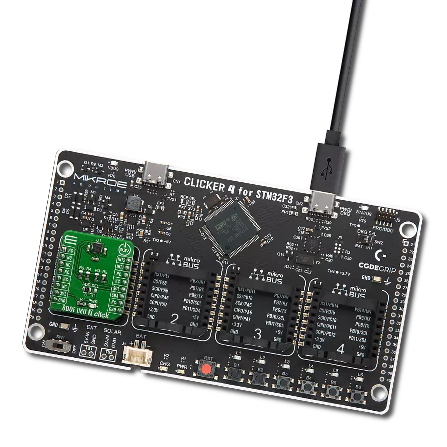
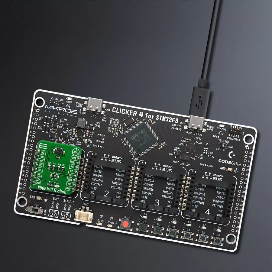
CLICKER 4 for STM32F302VCT6
Compiler
NECTO Studio
MCU
STM32F302VC
Enhance augmented reality (AR) experiences by accurately tracking user movements and surroundings, providing more realistic and interactive applications
A
A
Hardware Overview
How does it work?
6DOF IMU 7 Click is based on the ICM-20649, a high-performance, 6-axis MEMS MotionTracking™ from TDK InvenSense. It is an advanced, integrated microelectromechanical gyroscope and accelerometer sensor (MEMS). This allows very high integration and very small dimensions, at an affordable cost. The IC contains a MEMS structure hermetically sealed and bonded at wafer level. The ICM-20649 is the world’s first wide-range 6-axis MotionTracking device for Sports and other High Impact applications. It is available in a 3x3x0.9 mm 24-pin QFN package. Many of today’s wearable and sports solutions, which analyze the motion of a user’s golf or tennis swings, soccer ball kicks, or basketball activities, require higher than currently available ±2000 dps (degrees per second) FSR for gyroscope and ±16g FSR for accelerometer to better insure that critical data is not lost at the point of high impact or high speed rotation. The
ICM-20649 - 6-axis inertial sensor used on the 6DOF IMU 7 click offers the smallest size, lowest profile and lowest power in conjunction with industry leading high FSR. With an extended FSR range of ±4000 dps for gyroscope and ±30g for accelerometer, it enables precise analysis of contact sports applications providing continuous motion sensor data before, during and after impact providing more accurate feedback. ICM-20649 devices, with their 6-axis integration, on-chip DMP, and run-time calibration firmware, enable manufacturers to eliminate the costly and complex selection, qualification, and system level integration of discrete devices, guaranteeing optimal motion performance for consumers. The gyroscope has a programmable full-scale range up to ±4000 dps. The accelerometer has a user-programmable accelerometer full-scale range up to ±30g. Factory-calibrated initial sensitivity of
both sensors reduces production-line calibration requirements. Other key features include on-chip 16-bit ADCs, programmable digital filters, an embedded temperature sensor, and programmable interrupts. The embedded Digital Motion Processor (DMP) within the ICM-20649 offloads computation of motion processing algorithms from the host processor. The DMP acquires data from accelerometers, gyroscopes, and additional third party sensors such as magnetometers, and processes the data. The resulting data can be read from the 512 bytes FIFO that is accessible via the I2C Serial Interface. The FIFO configuration register determines which data is written into the FIFO. The interrupt function may be used to determine when new data is available.


Features overview
Development board
Clicker 4 for STM32F3 is a compact development board designed as a complete solution, you can use it to quickly build your own gadgets with unique functionalities. Featuring a STM32F302VCT6, four mikroBUS™ sockets for Click boards™ connectivity, power managment, and more, it represents a perfect solution for the rapid development of many different types of applications. At its core, there is a STM32F302VCT6 MCU, a powerful microcontroller by STMicroelectronics, based on the high-
performance Arm® Cortex®-M4 32-bit processor core operating at up to 168 MHz frequency. It provides sufficient processing power for the most demanding tasks, allowing Clicker 4 to adapt to any specific application requirements. Besides two 1x20 pin headers, four improved mikroBUS™ sockets represent the most distinctive connectivity feature, allowing access to a huge base of Click boards™, growing on a daily basis. Each section of Clicker 4 is clearly marked, offering an intuitive and clean interface. This makes working with the development
board much simpler and thus, faster. The usability of Clicker 4 doesn’t end with its ability to accelerate the prototyping and application development stages: it is designed as a complete solution which can be implemented directly into any project, with no additional hardware modifications required. Four mounting holes [4.2mm/0.165”] at all four corners allow simple installation by using mounting screws. For most applications, a nice stylish casing is all that is needed to turn the Clicker 4 development board into a fully functional, custom design.

Microcontroller Overview
MCU Card / MCU

Architecture
ARM Cortex-M4
MCU Memory (KB)
256
Silicon Vendor
STMicroelectronics
Pin count
100
RAM (Bytes)
40960
Used MCU Pins
mikroBUS™ mapper
Take a closer look
Click board™ Schematic

Step by step
Project assembly

Start by selecting your development board and Click board™. Begin with the CLICKER 4 for STM32F302VCT6 as your development board.


Software Support
Library Description
This library contains API for 6DOF IMU 7 Click driver.
Key functions:
c6dofimu7_get_gyro_data- This function reads gyroscope axis data and configures the gyro axis structc6dofimu7_get_accel_data- This function reads accelerometer axis data and configures the accel axis structc6dofimu7_get_temp_data- This function reads and returns temperature data
Open Source
Code example
The complete application code and a ready-to-use project are available through the NECTO Studio Package Manager for direct installation in the NECTO Studio. The application code can also be found on the MIKROE GitHub account.
/*!
 * \file
 * \brief 6DofImu7 Click example
 *
 * # Description
 * This example showcases how to initialize and configure the logger and Click modules and read
 * and display temperature measurements and axis data from the gyroscope and accelerometer.
 *
 * The demo application is composed of two sections :
 *
 * ## Application Init
 * This function initializes and configures the logger and Click modules.
 *
 * ## Application Task
 * This function reads and displays accelerometer, gyroscope and temperature data every second.
 *
 * \author MikroE Team
 *
 */
// ------------------------------------------------------------------- INCLUDES

#include "board.h"
#include "log.h"
#include "c6dofimu7.h"

// ------------------------------------------------------------------ VARIABLES

static c6dofimu7_t c6dofimu7;
static log_t logger;
static c6dofimu7_axis_t gyro;
static c6dofimu7_axis_t accel;

// ------------------------------------------------------ APPLICATION FUNCTIONS

void application_init ( )
{
    log_cfg_t log_cfg;
    c6dofimu7_cfg_t cfg;

    /**
     * Logger initialization.
     * Default baud rate: 115200
     * Default log level: LOG_LEVEL_DEBUG
     * @note If USB_UART_RX and USB_UART_TX
     * are defined as HAL_PIN_NC, you will
     * need to define them manually for log to work.
     * See @b LOG_MAP_USB_UART macro definition for detailed explanation.
     */
    LOG_MAP_USB_UART( log_cfg );
    log_init( &logger, &log_cfg );
    log_info( &logger, "---- Application Init ----" );

    //  Click initialization.

    c6dofimu7_cfg_setup( &cfg );
    C6DOFIMU7_MAP_MIKROBUS( cfg, MIKROBUS_1 );
    c6dofimu7_init( &c6dofimu7, &cfg );
    c6dofimu7_default_cfg( &c6dofimu7 );
}

void application_task ( )
{
    float temperature;

    c6dofimu7_get_gyro_data( &c6dofimu7, &gyro, C6DOFIMU7_GYRO_SENSITIVITY );

    log_printf( &logger, " * Gyro_X: %.5f * \r\n", gyro.x_axis );
    log_printf( &logger, " * Gyro_Y: %.5f * \r\n", gyro.y_axis );
    log_printf( &logger, " * Gyro_Z: %.5f * \r\n", gyro.z_axis );
    log_printf( &logger, " ---------------------------- \r\n" );

    c6dofimu7_get_accel_data( &c6dofimu7, &accel, C6DOFIMU7_ACCEL_SENSITIVITY );

    log_printf( &logger, " * Accel_X: %.5f * \r\n", accel.x_axis );
    log_printf( &logger, " * Accel_Y: %.5f * \r\n", accel.y_axis );
    log_printf( &logger, " * Accel_Z: %.5f * \r\n", accel.z_axis );
    log_printf( &logger, " ---------------------------- \r\n" );

    temperature = c6dofimu7_get_temp_data( &c6dofimu7, C6DOFIMU7_TEMPERATURE_SENSITIVITY,
                                                       C6DOFIMU7_TEMPERATURE_OFFSET );

    log_printf( &logger, " * Temperature: %.5f C * \r\n\r\n", temperature );
    Delay_ms ( 1000 );
}

int main ( void )
{
    /* Do not remove this line or clock might not be set correctly. */
    #ifdef PREINIT_SUPPORTED
    preinit();
    #endif

    application_init( );

    for ( ; ; )
    {
        application_task( );
    }

    return 0;
}

// ------------------------------------------------------------------------ END
Additional Support
Resources
Category:Motion


