Embrace a smarter and more convenient way of life with HTU21DF and TM4C129ENCPDT
Experience the future of climate control today

Published Nov 08, 2023
Click board™
Temp&Hum 13 Click
Dev. board
Fusion for Tiva v8
Compiler
NECTO Studio
MCU
TM4C129ENCPDT
Take control of your surroundings and make data-driven decisions for maximum comfort and productivity.
A
A
Hardware Overview
How does it work?
Temp&Hum 13 Click is based on the HTU21DF, a digital relative humidity sensor with temperature output from TE Connectivity. This sensor is factory calibrated to ±2% relative humidity and ±0.3°C temperature accuracy. It has an integrated heating element that is used for functionality diagnosis as well. This heating element can be simply activated by setting a bit in the appropriate register. In the case when the heater is powered on, the typical power consumption is about 5.5mW. Internally, two sensors are connected to the two separated ADC sections with variable resolution of 12 -14 bits for the temperature and 8-12 bits for relative humiditiy measurement. The OTP memory holds the calibration coefficients that are applied to the measured value and the results are stored on the output registers, in the MSB/LSB format. These values are then used in formulas found in the HTU21DF datasheet so that the final temperature or relative humidity data can be
calculated. It is also possible to correct the offsets with custom values. Temp&Hum 13 click uses the I2C protocol to communicate with the host MCU. Its I2C bus pins are routed to the mikroBUS™ I2C pins and are pulled to a HIGH logic level by the onboard resistors. The final I2C address of this IC is factory determined. There are two different operation modes to communicate with the HTU21D sensor: Hold Master mode and No Hold Master mode. In the first case, the SCK line is blocked (controlled by HTU21D(F) sensor) during measurement process while in the second case the SCK line remain open for other communication while the sensor is processing the measurement. The HTU21DF IC itself is a very low power consumption device and it can work in two modes: sleep and active (measurement) mode. The device enters the sleep the mode as soon as possible, to save power. This makes the HTU21DF suitable to be used in battery-powered applications. In these
applications, the HTU21DF spends most of the time in sleep mode, with the typical current consumption of 20 nA. While in the active mode, the typical current consumption is 450µA. The provided Click board™ library contains simple and easy to use functions, which simplify configuring and reading of the measurement data. These functions are demonstrated in the included example application and can be used as a reference for custom projects. These functions can be used in mikroC, mikroBasic and mikroPascal compilers for all MCU architectures, supported by MikroElektronika. This Click Board™ is designed to be operated only with 3.3V logic level. A proper logic voltage level conversion should be performed before the Click board™ is used with MCUs with logic levels of 5V. It is ready to be used as soon as it is inserted into a mikroBUS™ socket of the development system.

Features overview
Development board
Fusion for TIVA v8 is a development board specially designed for the needs of rapid development of embedded applications. It supports a wide range of microcontrollers, such as different 32-bit ARM® Cortex®-M based MCUs from Texas Instruments, regardless of their number of pins, and a broad set of unique functions, such as the first-ever embedded debugger/programmer over a WiFi network. The development board is well organized and designed so that the end-user has all the necessary elements, such as switches, buttons, indicators, connectors, and others, in one place. Thanks to innovative manufacturing technology, Fusion for TIVA v8 provides a fluid and immersive working experience, allowing access
anywhere and under any circumstances at any time. Each part of the Fusion for TIVA v8 development board contains the components necessary for the most efficient operation of the same board. An advanced integrated CODEGRIP programmer/debugger module offers many valuable programming/debugging options, including support for JTAG, SWD, and SWO Trace (Single Wire Output)), and seamless integration with the Mikroe software environment. Besides, it also includes a clean and regulated power supply module for the development board. It can use a wide range of external power sources, including a battery, an external 12V power supply, and a power source via the USB Type-C (USB-C) connector.
Communication options such as USB-UART, USB HOST/DEVICE, CAN (on the MCU card, if supported), and Ethernet is also included. In addition, it also has the well-established mikroBUS™ standard, a standardized socket for the MCU card (SiBRAIN standard), and two display options for the TFT board line of products and character-based LCD. Fusion for TIVA v8 is an integral part of the Mikroe ecosystem for rapid development. Natively supported by Mikroe software tools, it covers many aspects of prototyping and development thanks to a considerable number of different Click boards™ (over a thousand boards), the number of which is growing every day.

Microcontroller Overview
MCU Card / MCU

Type
8th Generation
Architecture
ARM Cortex-M4
MCU Memory (KB)
1024
Silicon Vendor
Texas Instruments
Pin count
128
RAM (Bytes)
262144
Used MCU Pins
mikroBUS™ mapper
Take a closer look
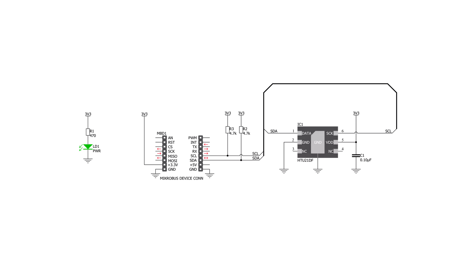
Click board™ Schematic
Step by step
Project assembly

Start by selecting your development board and Click board™. Begin with the Fusion for Tiva v8 as your development board.


Track your results in real time
Application Output
1. Application Output - In Debug mode, the 'Application Output' window enables real-time data monitoring, offering direct insight into execution results. Ensure proper data display by configuring the environment correctly using the provided tutorial.

2. UART Terminal - Use the UART Terminal to monitor data transmission via a USB to UART converter, allowing direct communication between the Click board™ and your development system. Configure the baud rate and other serial settings according to your project's requirements to ensure proper functionality. For step-by-step setup instructions, refer to the provided tutorial.

3. Plot Output - The Plot feature offers a powerful way to visualize real-time sensor data, enabling trend analysis, debugging, and comparison of multiple data points. To set it up correctly, follow the provided tutorial, which includes a step-by-step example of using the Plot feature to display Click board™ readings. To use the Plot feature in your code, use the function: plot(*insert_graph_name*, variable_name);. This is a general format, and it is up to the user to replace 'insert_graph_name' with the actual graph name and 'variable_name' with the parameter to be displayed.

Software Support
Library Description
This library contains API for Temp&Hum 13 Click driver.
Key functions:
temphum13_get_humidity- This function calculates humidity.temphum13_get_temperature-This function calculates current temperature.temphum13_change_resolution- This function sets click measurement resolution.
Open Source
Code example
The complete application code and a ready-to-use project are available through the NECTO Studio Package Manager for direct installation in the NECTO Studio. The application code can also be found on the MIKROE GitHub account.
/*!
 * \file
 * \brief TempHum13 Click example
 *
 * # Description
 * This demo shows basic TempHum13 Click functionality - temperature
 * and humidity measurement.
 *
 * The demo application is composed of two sections :
 *
 * ## Application Init
 * Initialize device.
 *
 * ## Application Task
 * Measure temperature and humidity values on every 0,5 seconds,
 * and log them to UART Terminal if they are valid.
 *
 *
 * \author MikroE Team
 *
 */
// ------------------------------------------------------------------- INCLUDES

#include "board.h"
#include "log.h"
#include "temphum13.h"

// ------------------------------------------------------------------ VARIABLES

static temphum13_t temphum13;
static log_t logger;

static float temperature;
static float humidity;

// ------------------------------------------------------ APPLICATION FUNCTIONS

void application_init ( void )
{
    log_cfg_t log_cfg;
    temphum13_cfg_t cfg;

    /**
     * Logger initialization.
     * Default baud rate: 115200
     * Default log level: LOG_LEVEL_DEBUG
     * @note If USB_UART_RX and USB_UART_TX
     * are defined as HAL_PIN_NC, you will
     * need to define them manually for log to work.
     * See @b LOG_MAP_USB_UART macro definition for detailed explanation.
     */
    LOG_MAP_USB_UART( log_cfg );
    log_init( &logger, &log_cfg );
    log_info( &logger, "---- Application Init ----" );

    //  Click initialization.

    temphum13_cfg_setup( &cfg );
        Delay_ms ( 500 );
    TEMPHUM13_MAP_MIKROBUS( cfg, MIKROBUS_1 );
        Delay_ms ( 500 );
    temphum13_init( &temphum13, &cfg );
        Delay_ms ( 500 );

    temphum13_default_cfg( &temphum13 );
}

void application_task ( void )
{
    temperature = temphum13_get_temperature( &temphum13 );
    humidity = temphum13_get_humidity( &temphum13 );

    if ( temperature != 65536.0 )
    {
        log_printf( &logger, "\r\n> Temperature : %.2f C", temperature );
    }

    if ( humidity != 65536.0 )
    {
        log_printf( &logger, "\r\n> Humidity    : %.2f%%RH\r\n", humidity );
    }

    Delay_ms ( 500 );
}

int main ( void )
{
    /* Do not remove this line or clock might not be set correctly. */
    #ifdef PREINIT_SUPPORTED
    preinit();
    #endif

    application_init( );

    for ( ; ; )
    {
        application_task( );
    }

    return 0;
}

// ------------------------------------------------------------------------ END
Additional Support
Resources
Category:Temperature & humidity


