Achieve accurate and stable inertial movement measurements with ICM-45605 and STM32F415ZG
Understand the device's movement in three-dimensional space

Published Jan 05, 2024
Click board™
6DOF IMU 16 Click
Dev. board
UNI-DS v8
Compiler
NECTO Studio
MCU
STM32F415ZG
Unlock advanced motion sensing to precisely track and interpret your device's movement in three-dimensional space for applications ranging from virtual reality to wearables and IoT devices
A
A
Hardware Overview
How does it work?
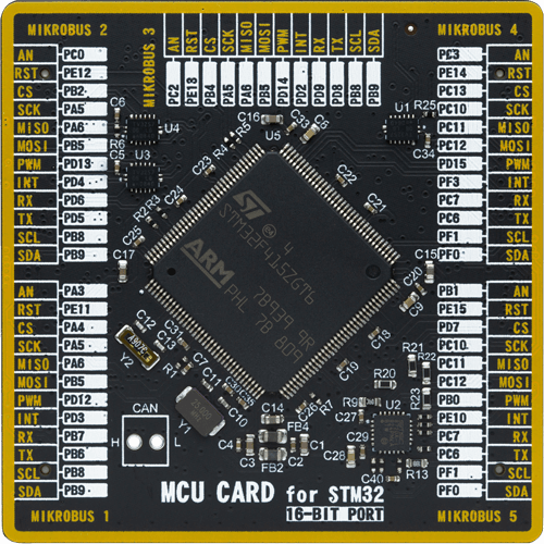
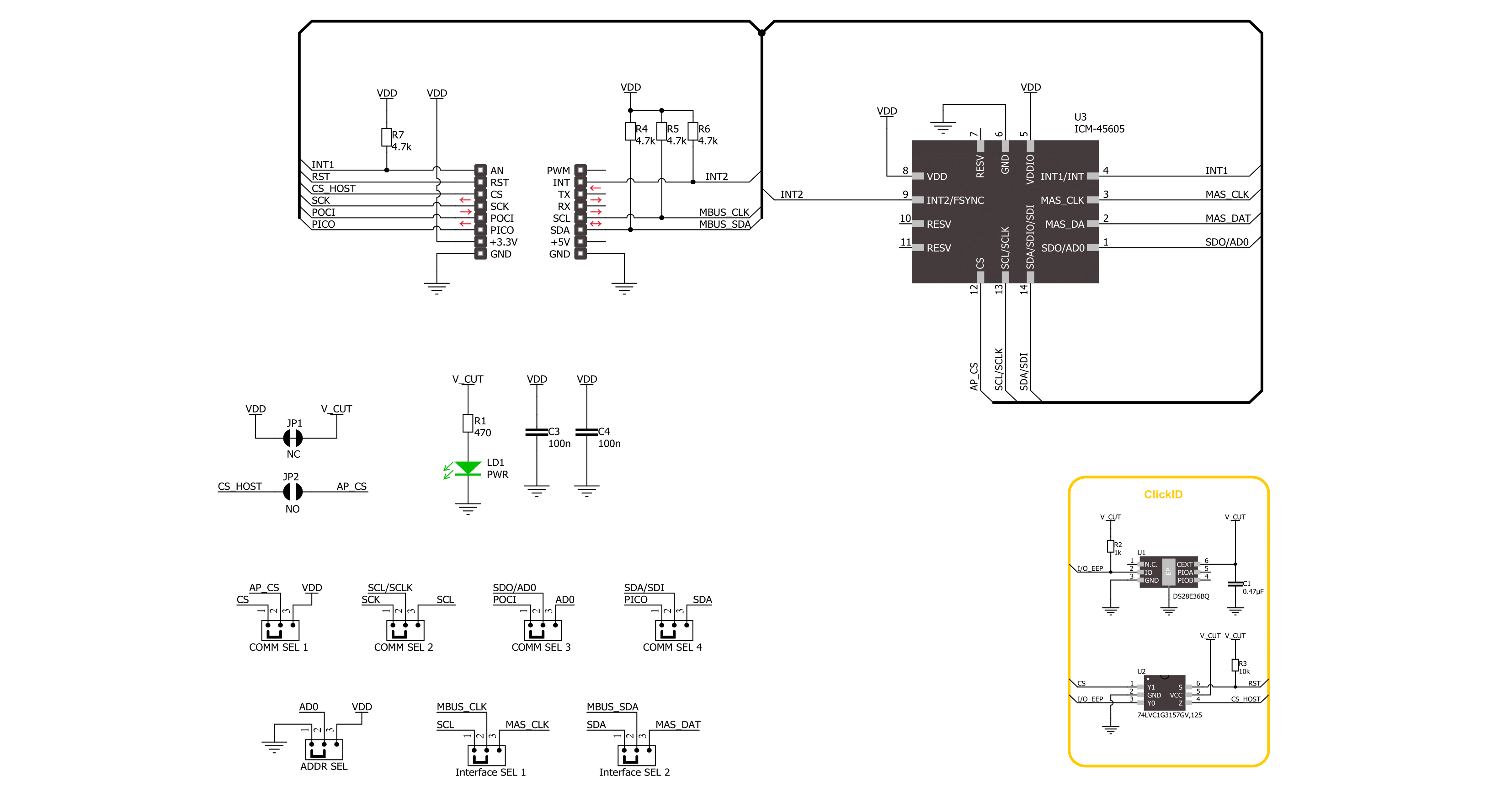
6DOF IMU 16 Click is based on the ICM-45605, an ultra-high-performance 6-axis MEMS IMU with the world's first BalancedGyro™ technology and the lowest power consumption from TDK InvenSense. The sensor combines a 3‑axis gyroscope and a 3‑axis accelerometer in a compact package. Thanks to the BalancedGyro™ technology, the gyroscope MEMS architecture, a supreme vibration rejection and temperature stability performance is achieved. It has a digital-output gyroscope angular rate with a programmable full-scale range of ±15.625, ±31.25, ±62.5, ±125, ±250, ±500, ±1000, and ±2000 degrees/sec. The accelerometer also has a digital output with a programmable full-scale range of ±2g, ±4g, ±8g, and ±16g. The ICM-45605's on-chip digital motion processor enables advanced motion algorithms and machine learning capability.
The sensors have a self-test, low noise power mode support, good sensitivity, and more. The ICM-45605 also includes the APEX motion features such as pedometer, tilt detection, raise to wake/sleep, tap detection, wake on motion, and more. In addition, there is also a FIFO buffer of up to 8KB, enabling the application MCU to read the data in bursts. 6DOF IMU 16 Click can use a standard 4-wire SPI serial interface to communicate with the host MCU supporting clock frequency of up to 24MHz. It can also use a standard 2-wire I2C supporting a maximum bus speed of 1MHz. The I2C address can be selected over the ADDR SEL jumper. The communication selection can be made over the COMM SEL jumpers. You can also choose between a single or dual interface over the Interface jumper. This allows
you to use an I2C interface as a host while using the SPI. The APEX hardware will interrupt the host MCU over two interrupt pins (I1 and I2) if an interrupt event occurs, such as tilt detection, tap, or whatever events are pre-programmed to those pins. At the bottom of the board, two LP CUT low-power jumpers allow you to use 6DOF IMU 16 Click in a true low-power mode or with a battery-powered device, such as our Clicker 2 series of development boards. This Click board™ can be operated only with a 3.3V logic voltage level. The board must perform appropriate logic voltage level conversion before using MCUs with different logic levels. Also, it comes equipped with a library containing functions and an example code that can be used as a reference for further development.

Features overview
Development board
UNI-DS v8 is a development board specially designed for the needs of rapid development of embedded applications. It supports a wide range of microcontrollers, such as different STM32, Kinetis, TIVA, CEC, MSP, PIC, dsPIC, PIC32, and AVR MCUs regardless of their number of pins, and a broad set of unique functions, such as the first-ever embedded debugger/programmer over WiFi. The development board is well organized and designed so that the end-user has all the necessary elements, such as switches, buttons, indicators, connectors, and others, in one place. Thanks to innovative manufacturing technology, UNI-DS v8 provides a fluid and immersive working experience, allowing access anywhere and under any
circumstances at any time. Each part of the UNI-DS v8 development board contains the components necessary for the most efficient operation of the same board. An advanced integrated CODEGRIP programmer/debugger module offers many valuable programming/debugging options, including support for JTAG, SWD, and SWO Trace (Single Wire Output)), and seamless integration with the Mikroe software environment. Besides, it also includes a clean and regulated power supply module for the development board. It can use a wide range of external power sources, including a battery, an external 12V power supply, and a power source via the USB Type-C (USB-C) connector. Communication options such as USB-UART, USB
HOST/DEVICE, CAN (on the MCU card, if supported), and Ethernet is also included. In addition, it also has the well-established mikroBUS™ standard, a standardized socket for the MCU card (SiBRAIN standard), and two display options for the TFT board line of products and character-based LCD. UNI-DS v8 is an integral part of the Mikroe ecosystem for rapid development. Natively supported by Mikroe software tools, it covers many aspects of prototyping and development thanks to a considerable number of different Click boards™ (over a thousand boards), the number of which is growing every day.

Microcontroller Overview
MCU Card / MCU
Type
8th Generation
Architecture
ARM Cortex-M4
MCU Memory (KB)
1024
Silicon Vendor
STMicroelectronics
Pin count
144
RAM (Bytes)
196608
Used MCU Pins
mikroBUS™ mapper
Take a closer look
Click board™ Schematic
Step by step
Project assembly

Start by selecting your development board and Click board™. Begin with the UNI-DS v8 as your development board.


Software Support
Library Description
This library contains API for 6DOF IMU 16 Click driver.
Key functions:
c6dofimu16_sw_reset- This function performs the device software reset.c6dofimu16_get_gyro_data- This function reads the angular rate of X, Y, and Z axis in degrees per second (mdps).c6dofimu16_get_accel_data- This function reads the accelerometer of X, Y, and Z axis relative to standard gravity (mg).
Open Source
Code example
The complete application code and a ready-to-use project are available through the NECTO Studio Package Manager for direct installation in the NECTO Studio. The application code can also be found on the MIKROE GitHub account.
/*!
 * @file main.c
 * @brief 6DOF IMU 16 Click example
 *
 * # Description
 * This example demonstrates the use of 6DOF IMU 16 Click board by reading and displaying
 * the accelerometer and gyroscope data (X, Y, and Z axis).
 *
 * The demo application is composed of two sections :
 *
 * ## Application Init
 * Initializes the driver performs the Click default configuration,
 * and checks communication by reading device ID.
 *
 * ## Application Task
 * Reading the accelerometer and gyroscope measurements, results are displayed on the USB UART every second.
 *
 * @author Stefan Ilic
 *
 */

#include "board.h"
#include "log.h"
#include "c6dofimu16.h"

static c6dofimu16_t c6dofimu16;
static log_t logger;

void application_init ( void )
{
    log_cfg_t log_cfg;  /**< Logger config object. */
    c6dofimu16_cfg_t c6dofimu16_cfg;  /**< Click config object. */

    /**
     * Logger initialization.
     * Default baud rate: 115200
     * Default log level: LOG_LEVEL_DEBUG
     * @note If USB_UART_RX and USB_UART_TX
     * are defined as HAL_PIN_NC, you will
     * need to define them manually for log to work.
     * See @b LOG_MAP_USB_UART macro definition for detailed explanation.
     */
    LOG_MAP_USB_UART( log_cfg );
    log_init( &logger, &log_cfg );
    log_info( &logger, " Application Init " );

    // Click initialization.
    c6dofimu16_cfg_setup( &c6dofimu16_cfg );
    C6DOFIMU16_MAP_MIKROBUS( c6dofimu16_cfg, MIKROBUS_1 );
    err_t init_flag = c6dofimu16_init( &c6dofimu16, &c6dofimu16_cfg );
    if ( ( I2C_MASTER_ERROR == init_flag ) || ( SPI_MASTER_ERROR == init_flag ) )
    {
        log_error( &logger, " Communication init." );
        for ( ; ; );
    }

    if ( C6DOFIMU16_ERROR == c6dofimu16_default_cfg ( &c6dofimu16 ) )
    {
        log_error( &logger, " Default configuration." );
        for ( ; ; );
    }

    uint8_t dev_id = 0;
    c6dofimu16_reg_read( &c6dofimu16, C6DOFIMU16_REG_WHO_AM_I, &dev_id );
    if ( C6DOFIMU16_DEVICE_ID != dev_id )
    {
        log_error( &logger, " Communication error " );
        for ( ; ; );
    }
    log_printf( &logger, " Device ID: 0x%.2X \r\n", ( uint16_t ) dev_id );


    log_info( &logger, " Application Task " );
}

void application_task ( void )
{
    c6dofimu16_axis_t accel_data;
    c6dofimu16_axis_t gyro_data;

    c6dofimu16_get_accel_data( &c6dofimu16, &accel_data );
    c6dofimu16_get_gyro_data( &c6dofimu16, &gyro_data );
    log_printf( &logger, " Accel data | Gyro data \r\n" );
    log_printf( &logger, " X: %.2f g  | %.2f dps \r\n", accel_data.x_data, gyro_data.x_data );
    log_printf( &logger, " Y: %.2f g  | %.2f dps \r\n", accel_data.y_data, gyro_data.y_data );
    log_printf( &logger, " Z: %.2f g  | %.2f dps \r\n", accel_data.z_data, gyro_data.z_data );
    Delay_ms ( 1000 );
}

int main ( void )
{
    /* Do not remove this line or clock might not be set correctly. */
    #ifdef PREINIT_SUPPORTED
    preinit();
    #endif

    application_init( );

    for ( ; ; )
    {
        application_task( );
    }

    return 0;
}

// ------------------------------------------------------------------------ END


