Achieve real-time monitoring of current levels with INA381 and TM4C129ENCPDT
Innovate with cutting-edge current sensing technology
Published Aug 09, 2023
Click board™
Current 5 Click
Dev. board
Fusion for Tiva v8
Compiler
NECTO Studio
MCU
TM4C129ENCPDT
Enhance your engineering expertise with the unwavering reliability and meticulous precision of our advanced current sensing solution
A
A
Hardware Overview
How does it work?
Current 5 Click is based on the INA381, a zero-drift topology, a current-sensing amplifier with an integrated comparator that can be used in both low-side and high-side current-sensing and protection applications from Texas Instruments. This current-sensing amplifier accurately measures voltages developed across the current-sensing resistor (also known as current-shunt resistors) on common-mode voltages far exceeding the device supply voltage. Current is measured on IN load connection terminal, withstanding the full common-mode voltages from –0.2V to +26V at the input pins when the supply voltage is removed without causing damage. The INA381 also uses a reference input from an onboard REF potentiometer that simplifies setting the corresponding current threshold level for out-of-range comparison. Combining the precision measurement of the current-sense amplifier and the onboard comparator enables an all-in-one overcurrent detection device. This combination creates a highly-accurate design that quickly detects out-of-range conditions and allows the system to take
corrective actions to prevent potential component or system-wide damage. The amplified output voltage of the INA381 is developed across the onboard current-sensing resistor, which is the input voltage across the IN terminal (IN+ and IN– pins) multiplied by the gain of the amplifier (200V/V). The output voltage of the INA381 is then converted to a digital value using the ADC121S021, a low-power, single-channel 12-bit analog to digital converter (ADC), with a high-speed SPI interface also from Texas Instruments. The INA381‘s integrated comparator is designed to quickly detect when the sense current is out-of-range, and provide an interrupt alert signal, routed to the INT pin of the mikroBUS™ socket, for quicker and faster responses. This alert output can be configured to operate in two modes, transparent or latched, selectable according to the logic state on the RST pin of the mikroBUS™ socket. In transparent mode, the output status follows the input state, while in latched mode, the alert output is cleared only when the latch is reset. The onboard comparator in the INA381 is designed to reduce the possibility of oscillations in the
alert output when the measured signal level is near the over-limit threshold level due to noise, with a hysteresis of 50mV. When the voltage on the comparator input exceeds the voltage developed at the comparator reference input, the alert signal sets to a low logic state. The output voltage then must drop to less than the reference input threshold voltage by the hysteresis level of 50mV so that the alert pin de-asserts and returns to the nominal high state. Also, this board allows the user to change the hysteresis from a preset value of 50mV via an onboard Hyst potentiometer. The user can also bring external signals, such as REF and HYST, on the eponymous onboard headers. This Click board™ can operate with either 3.3V or 5V logic voltage levels selected via the VCC SEL jumper. This way, both 3.3V and 5V capable MCUs can use the communication lines properly. Also, this Click board™ comes equipped with a library containing easy-to-use functions and an example code that can be used, as a reference, for further development.

Features overview
Development board
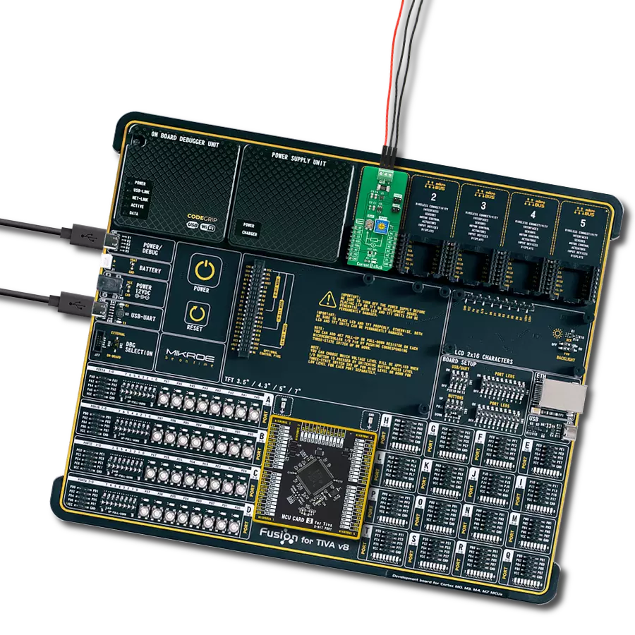
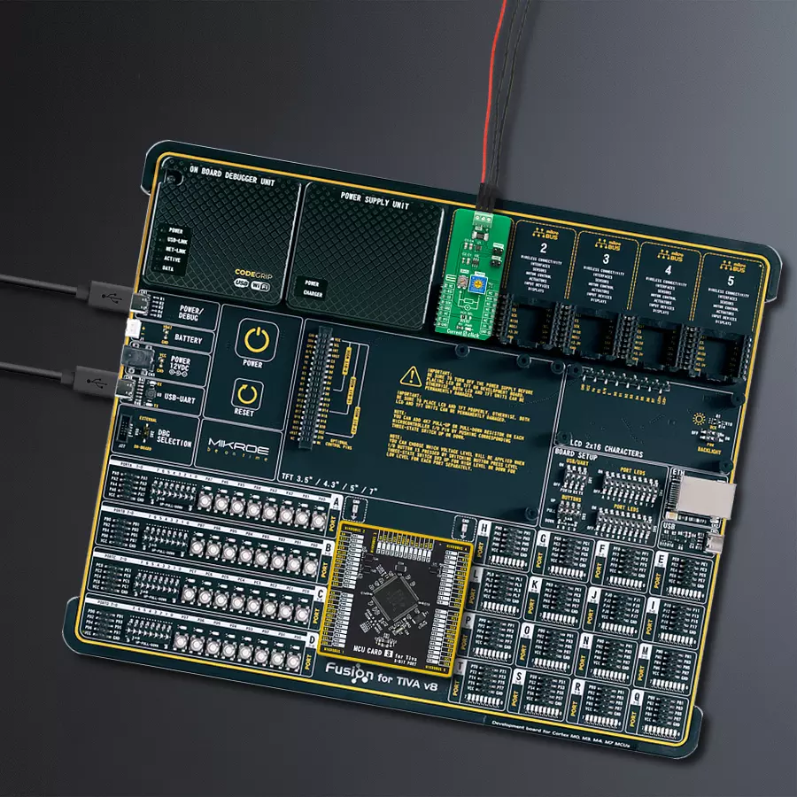
Fusion for TIVA v8 is a development board specially designed for the needs of rapid development of embedded applications. It supports a wide range of microcontrollers, such as different 32-bit ARM® Cortex®-M based MCUs from Texas Instruments, regardless of their number of pins, and a broad set of unique functions, such as the first-ever embedded debugger/programmer over a WiFi network. The development board is well organized and designed so that the end-user has all the necessary elements, such as switches, buttons, indicators, connectors, and others, in one place. Thanks to innovative manufacturing technology, Fusion for TIVA v8 provides a fluid and immersive working experience, allowing access
anywhere and under any circumstances at any time. Each part of the Fusion for TIVA v8 development board contains the components necessary for the most efficient operation of the same board. An advanced integrated CODEGRIP programmer/debugger module offers many valuable programming/debugging options, including support for JTAG, SWD, and SWO Trace (Single Wire Output)), and seamless integration with the Mikroe software environment. Besides, it also includes a clean and regulated power supply module for the development board. It can use a wide range of external power sources, including a battery, an external 12V power supply, and a power source via the USB Type-C (USB-C) connector.
Communication options such as USB-UART, USB HOST/DEVICE, CAN (on the MCU card, if supported), and Ethernet is also included. In addition, it also has the well-established mikroBUS™ standard, a standardized socket for the MCU card (SiBRAIN standard), and two display options for the TFT board line of products and character-based LCD. Fusion for TIVA v8 is an integral part of the Mikroe ecosystem for rapid development. Natively supported by Mikroe software tools, it covers many aspects of prototyping and development thanks to a considerable number of different Click boards™ (over a thousand boards), the number of which is growing every day.

Microcontroller Overview
MCU Card / MCU

Type
8th Generation
Architecture
ARM Cortex-M4
MCU Memory (KB)
1024
Silicon Vendor
Texas Instruments
Pin count
128
RAM (Bytes)
262144
Used MCU Pins
mikroBUS™ mapper
Take a closer look
Click board™ Schematic

Step by step
Project assembly

Start by selecting your development board and Click board™. Begin with the Fusion for Tiva v8 as your development board.


Software Support
Library Description
This library contains API for Current 5 Click driver.
Key functions:
current5_get_current- Get currentcurrent5_get_adc- Read raw adc valuecurrent5_get_alert- Get alert pin state
Open Source
Code example
The complete application code and a ready-to-use project are available through the NECTO Studio Package Manager for direct installation in the NECTO Studio. The application code can also be found on the MIKROE GitHub account.
/*!
* @file main.c
* @brief Current5 Click example
*
* # Description
* This example application showcases ability of the device
* to read raw adc data and calculate the current from it.
*
* The demo application is composed of two sections :
*
* ## Application Init
* Initialization of communication modules(SPI, UART) and
* additional pins for controlling device(RST, ALERT->INT).
*
* ## Application Task
* Read ADC data with SPI communication and calculate input current.
*
* @author Luka Filipovic
*
*/
#include "board.h"
#include "log.h"
#include "current5.h"
static current5_t current5;
static log_t logger;
void application_init ( void )
{
log_cfg_t log_cfg; /**< Logger config object. */
current5_cfg_t current5_cfg; /**< Click config object. */
/**
* Logger initialization.
* Default baud rate: 115200
* Default log level: LOG_LEVEL_DEBUG
* @note If USB_UART_RX and USB_UART_TX
* are defined as HAL_PIN_NC, you will
* need to define them manually for log to work.
* See @b LOG_MAP_USB_UART macro definition for detailed explanation.
*/
LOG_MAP_USB_UART( log_cfg );
log_init( &logger, &log_cfg );
log_info( &logger, " Application Init " );
// Click initialization.
current5_cfg_setup( ¤t5_cfg );
CURRENT5_MAP_MIKROBUS( current5_cfg, MIKROBUS_1 );
err_t init_flag = current5_init( ¤t5, ¤t5_cfg );
if ( SPI_MASTER_ERROR == init_flag )
{
log_error( &logger, " Application Init Error. " );
log_info( &logger, " Please, run program again... " );
for ( ; ; );
}
log_info( &logger, " Application Task " );
}
void application_task ( void )
{
float current = 0;
current5_get_current( ¤t5, ¤t );
log_printf( &logger, " > Current[ A ]: %.2f\r\n", current );
log_printf( &logger, "*************************************************\r\n" );
Delay_ms ( 300 );
}
int main ( void )
{
/* Do not remove this line or clock might not be set correctly. */
#ifdef PREINIT_SUPPORTED
preinit();
#endif
application_init( );
for ( ; ; )
{
application_task( );
}
return 0;
}
// ------------------------------------------------------------------------ END
Additional Support
Resources
Category:Current sensor


