Ensure optimal power delivery with LT3976 and STM32L496AG
Step down, Power up!
Published Jul 22, 2025
Click board™
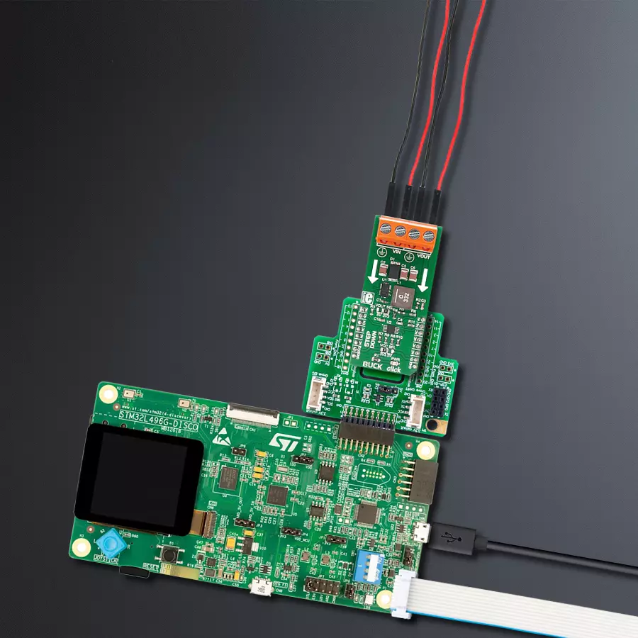
BUCK Click
Dev. board
Discovery kit with STM32L496AG MCU
Compiler
NECTO Studio
MCU
STM32L496AG
With its compact design and high efficiency, our step-down buck converter is the go-to solution for portable electronic devices, extending battery life while maintaining performance
A
A
Hardware Overview
How does it work?
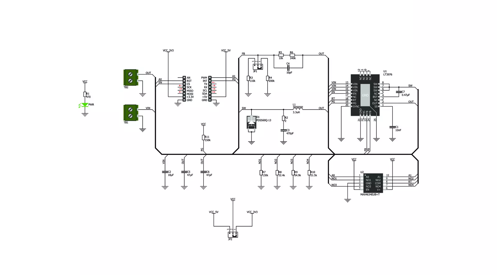
BUCK Click is based on the LT3976, a buck switching regulator from Analog Devices that accepts a wide input voltage range of up to 40V and steps it down to 3.3V or 5V. BUCK Click communicates with the target microcontroller over the following pins on the mikroBUS™ line: PWM, INT, RS, CS. The LT3976 is an adjustable frequency monolithic buck-switching regulator that accepts a wide input voltage range of up to 40V. Low quiescent current design consumes only
3.3µA of supply current while regulating with no load. Low ripple Burst Mode operation maintains high efficiency at low output currents while keeping the output ripple below 15mV in a typical application. The LT3976 can supply up to 5A of load current and has current limit foldback to limit power dissipation during short-circuit. A low dropout voltage of 500mV is maintained when the input voltage drops below the programmed output voltage, such as during an automotive cold
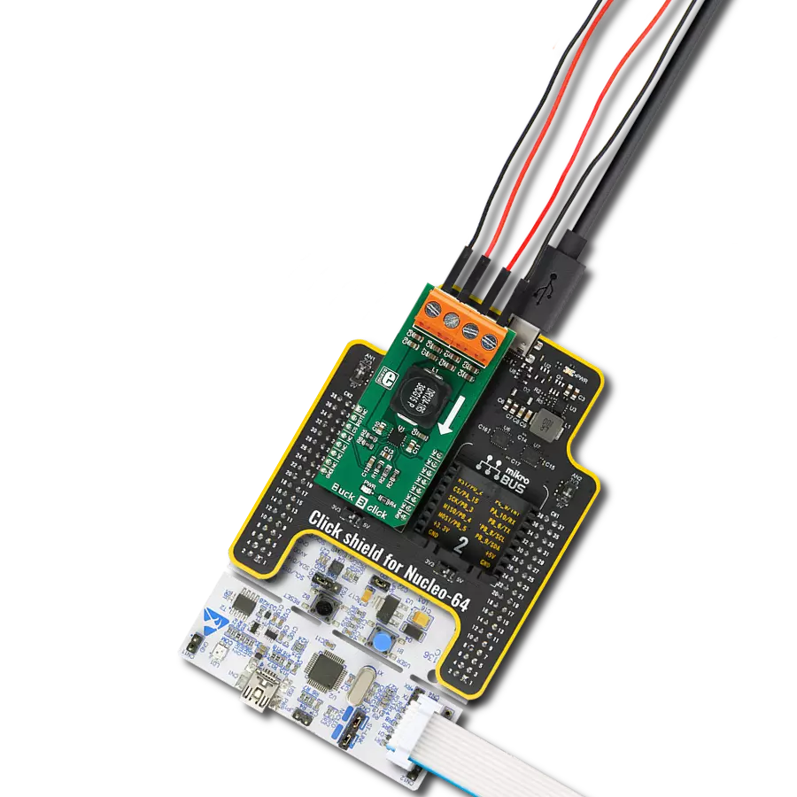
crank. There are two onboard screw terminals, one for connecting the external input supply and the other for the output. A multiplexer also chooses the resistor used for setting the switching frequency. The multiplexer is used for selecting one of the four different resistors. Each of these resistors, if selected, sets a different switching frequency from 0.4 to 1.6MHz.

Features overview
Development board
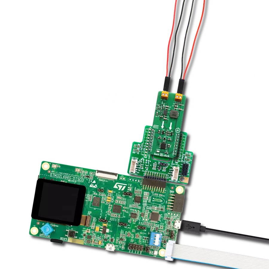
The 32L496GDISCOVERY Discovery kit serves as a comprehensive demonstration and development platform for the STM32L496AG microcontroller, featuring an Arm® Cortex®-M4 core. Designed for applications that demand a balance of high performance, advanced graphics, and ultra-low power consumption, this kit enables seamless prototyping for a wide range of embedded solutions. With its innovative energy-efficient
architecture, the STM32L496AG integrates extended RAM and the Chrom-ART Accelerator, enhancing graphics performance while maintaining low power consumption. This makes the kit particularly well-suited for applications involving audio processing, graphical user interfaces, and real-time data acquisition, where energy efficiency is a key requirement. For ease of development, the board includes an onboard ST-LINK/V2-1
debugger/programmer, providing a seamless out-of-the-box experience for loading, debugging, and testing applications without requiring additional hardware. The combination of low power features, enhanced memory capabilities, and built-in debugging tools makes the 32L496GDISCOVERY kit an ideal choice for prototyping advanced embedded systems with state-of-the-art energy efficiency.

Microcontroller Overview
MCU Card / MCU

Architecture
ARM Cortex-M4
MCU Memory (KB)
1024
Silicon Vendor
STMicroelectronics
Pin count
169
RAM (Bytes)
327680
Used MCU Pins
mikroBUS™ mapper
Take a closer look
Click board™ Schematic
Step by step
Project assembly

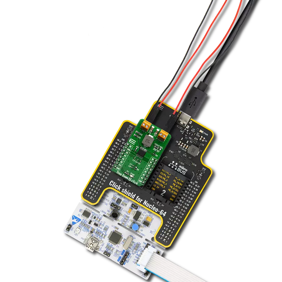
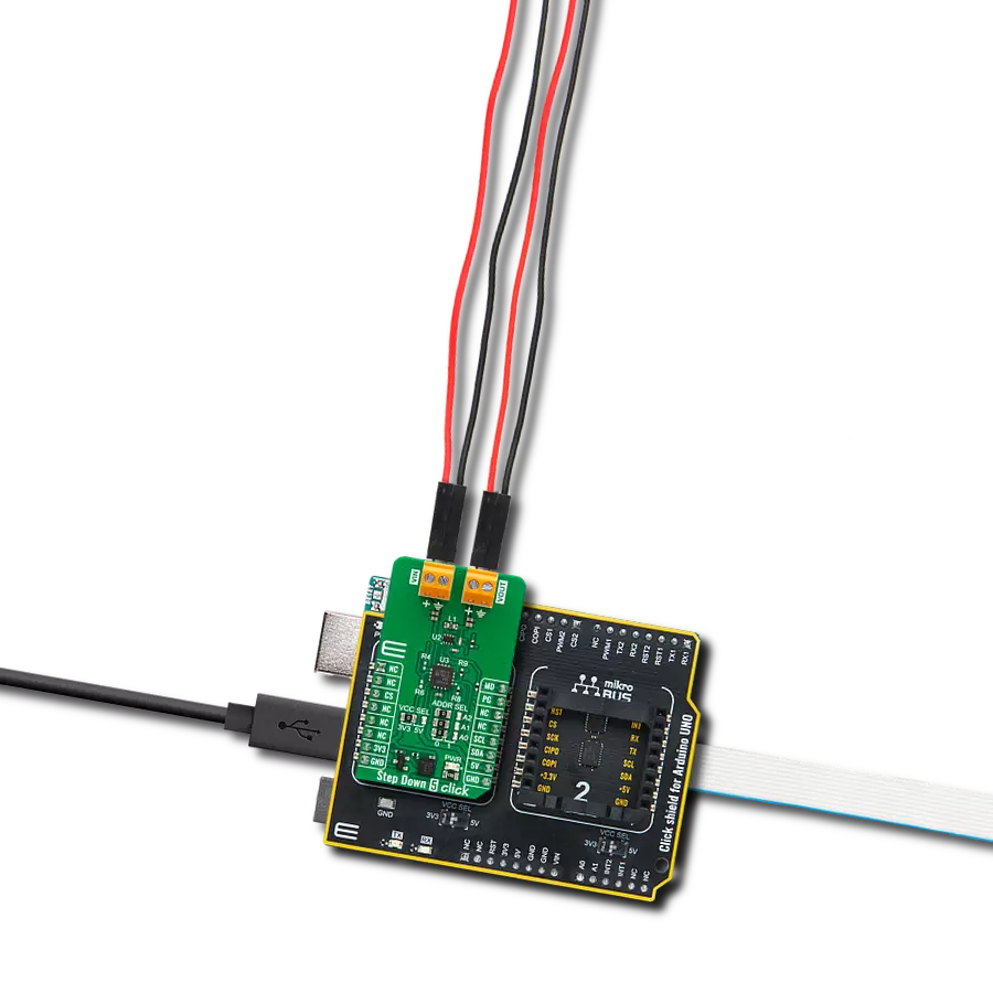
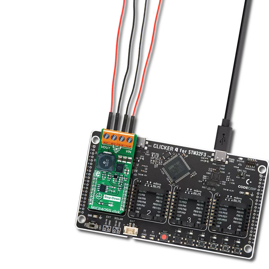
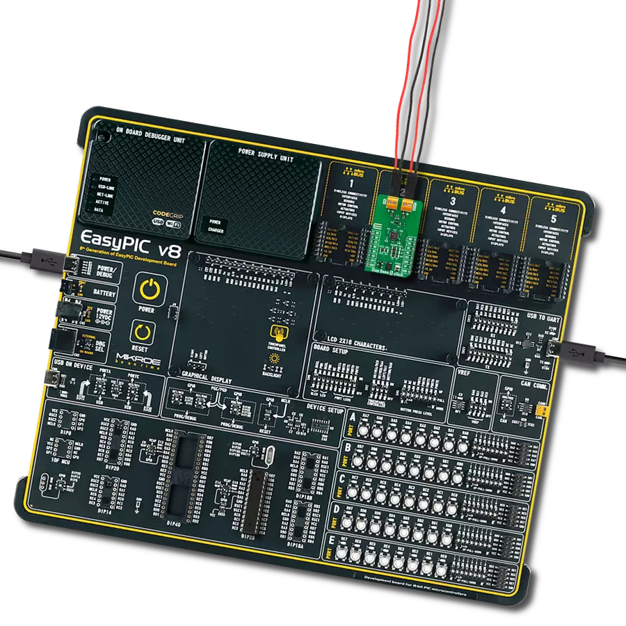
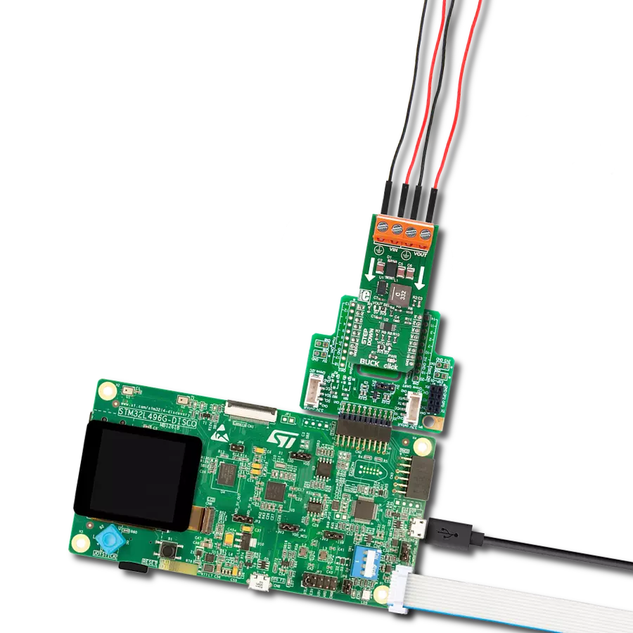
Start by selecting your development board and Click board™. Begin with the Discovery kit with STM32L496AG MCU as your development board.


Track your results in real time
Application Output
1. Application Output - In Debug mode, the 'Application Output' window enables real-time data monitoring, offering direct insight into execution results. Ensure proper data display by configuring the environment correctly using the provided tutorial.

2. UART Terminal - Use the UART Terminal to monitor data transmission via a USB to UART converter, allowing direct communication between the Click board™ and your development system. Configure the baud rate and other serial settings according to your project's requirements to ensure proper functionality. For step-by-step setup instructions, refer to the provided tutorial.

3. Plot Output - The Plot feature offers a powerful way to visualize real-time sensor data, enabling trend analysis, debugging, and comparison of multiple data points. To set it up correctly, follow the provided tutorial, which includes a step-by-step example of using the Plot feature to display Click board™ readings. To use the Plot feature in your code, use the function: plot(*insert_graph_name*, variable_name);. This is a general format, and it is up to the user to replace 'insert_graph_name' with the actual graph name and 'variable_name' with the parameter to be displayed.

Software Support
Library Description
This library contains API for BUCK Click driver.
Key functions:
buck_switch_frequency- Setting the switching frequency functionbuck_set_mode- Select buck mode (Disable / Enable)buck_get_power_good- Get state internal comparator function
Open Source
Code example
The complete application code and a ready-to-use project are available through the NECTO Studio Package Manager for direct installation in the NECTO Studio. The application code can also be found on the MIKROE GitHub account.
/*!
 * \file
 * \brief BUCK Click example
 *
 * # Description
 * The demo application displays frequency change and voltage
 * regulation using a BUCK Click.
 *
 * The demo application is composed of two sections :
 *
 * ## Application Init
 * Configuring Clicks and log objects.
 * Settings the Click in the default configuration.
 *
 * ## Application Task
 * This is a example which demonstrates the use of Buck Click board.
 * Checks if it has reached the set output voltage and sets
 * a different frequency to the LT3976 chip every 5 sec.
 *
 * \author Katarina Perendic
 *
 */
// ------------------------------------------------------------------- INCLUDES

#include "board.h"
#include "log.h"
#include "buck.h"

// ------------------------------------------------------------------ VARIABLES

static buck_t buck;
static log_t logger;

// ------------------------------------------------------ APPLICATION FUNCTIONS

void application_init ( void )
{
    log_cfg_t log_cfg;
    buck_cfg_t cfg;

    /**
     * Logger initialization.
     * Default baud rate: 115200
     * Default log level: LOG_LEVEL_DEBUG
     * @note If USB_UART_RX and USB_UART_TX
     * are defined as HAL_PIN_NC, you will
     * need to define them manually for log to work.
     * See @b LOG_MAP_USB_UART macro definition for detailed explanation.
     */
    LOG_MAP_USB_UART( log_cfg );
    log_init( &logger, &log_cfg );
    log_info( &logger, "---- Application Init ----" );

    //  Click initialization.

    buck_cfg_setup( &cfg );
    BUCK_MAP_MIKROBUS( cfg, MIKROBUS_1 );
    buck_init( &buck, &cfg );
    Delay_ms ( 100 );

    buck_device_reset( &buck );
    buck_default_cfg( &buck );
}

void application_task ( void )
{
    //  Task implementation.
    if ( buck_get_power_good( &buck ) == 1 )
    {
        log_info( &logger, "----  Power good output voltage!  ----" );
    }
    Delay_ms ( 1000 );

    log_info( &logger, "----  Switching frequency 400kHz!  ----" );
    buck_switch_frequency( &buck, BUCK_FREQ_400KHz );
    Delay_ms ( 1000 );
    Delay_ms ( 1000 );
    Delay_ms ( 1000 );
    Delay_ms ( 1000 );
    Delay_ms ( 1000 );

    log_info( &logger, "----  Switching frequency 800kHz!  ----" );
    buck_switch_frequency( &buck, BUCK_FREQ_800KHz );
    Delay_ms ( 1000 );
    Delay_ms ( 1000 );
    Delay_ms ( 1000 );
    Delay_ms ( 1000 );
    Delay_ms ( 1000 );
}

int main ( void )
{
    /* Do not remove this line or clock might not be set correctly. */
    #ifdef PREINIT_SUPPORTED
    preinit();
    #endif

    application_init( );

    for ( ; ; )
    {
        application_task( );
    }

    return 0;
}


// ------------------------------------------------------------------------ END
Additional Support
Resources
Category:Buck