Boost your performance with MCP1665 and TM4C129ENCPDT
Reach new heights!

Published Jul 25, 2023
Click board™
Step Up Click
Dev. board
Fusion for Tiva v8
Compiler
NECTO Studio
MCU
TM4C129ENCPDT
Take your power management to the next level and add a nonsynchronous step-up DC-DC converter to your solution
A
A
Hardware Overview
How does it work?
Step Up Click is based on the MCP1665, a 500kHz, compact, high-efficiency, fixed-frequency, nonsynchronous step-up DC/DC converter that integrates a 36V, 100 mΩ NMOS switch from Microchip. This IC is targeted towards boosting the voltage from NiCd, NiMH, and Li-Po/Li-Ion batteries, and as such, it has a great efficiency factor that allows for prolonged battery life. The MCP1665 uses a fixed switching frequency of 500kHz and has overvoltage protection to ensure safe operation. Thanks to the undervoltage lockout feature, the voltage step-up process starts with an input voltage as low as 2.7V. The MCP1665 features a UVLO that prevents fault operation below 2.7V, which corresponds to the value of three discharged primary Ni-Cd cells. The device starts its normal operation at 2.85V (typical) input. The device should be powered with at least 2.85V at the input terminal for optimal efficiency.
Output current depends on the input and desired output voltage; for example, when powered with 4V at the input, the Step Up click will deliver about 1A with 12V to the connected load. As with most step-up regulators, the input voltage should always be less than the voltage at the output to maintain the proper regulation. The MCP1665 step-up regulator actively damps the oscillations typically found at the switch node of a boost converter. This removes the high-frequency radiated noise, ensuring low-noise operation. Besides the MCP1665, Step Up 2 Click also contains the D/A converter (DAC) labeled as MCP4921, 12-Bit DACs with the SPI Interface by Microchip, used in a feedback loop. The DACs are connected to the boost converter's feedback loop; therefore, the DAC signal, which commonly ranges from 0 to +VREF, influences the voltage on the feedback midpoint. That way, the output voltage can be
set to a desired value, up to 30V. The mentioned DAC uses SPI communication, so the SDI, SDO, SCK, and CS pin of the mikroBUS™ are used for communication with the main MCU. The device also features the mode pin, labeled MOD, constructed as the open-drain output, pulled HIGH by the onboard 10K resistor. This allows easy interfacing with the MCU and a simple solution to have control over the switching mode. When the MOD pin is set to a logic high level, the device switches in PFM for a light load. The MOD pin is routed to the mikroBUS™ RST pin. Besides the mode pin, the EN pin used to enable the device is routed to the mikroBUS™ CS pin. When pulled LOW, this pin will engage the true disconnect of the output load option, resulting in low quintessential currents suitable for battery-operated devices. This pin is also pulled HIGH by the onboard resistor.

Features overview
Development board
Fusion for TIVA v8 is a development board specially designed for the needs of rapid development of embedded applications. It supports a wide range of microcontrollers, such as different 32-bit ARM® Cortex®-M based MCUs from Texas Instruments, regardless of their number of pins, and a broad set of unique functions, such as the first-ever embedded debugger/programmer over a WiFi network. The development board is well organized and designed so that the end-user has all the necessary elements, such as switches, buttons, indicators, connectors, and others, in one place. Thanks to innovative manufacturing technology, Fusion for TIVA v8 provides a fluid and immersive working experience, allowing access
anywhere and under any circumstances at any time. Each part of the Fusion for TIVA v8 development board contains the components necessary for the most efficient operation of the same board. An advanced integrated CODEGRIP programmer/debugger module offers many valuable programming/debugging options, including support for JTAG, SWD, and SWO Trace (Single Wire Output)), and seamless integration with the Mikroe software environment. Besides, it also includes a clean and regulated power supply module for the development board. It can use a wide range of external power sources, including a battery, an external 12V power supply, and a power source via the USB Type-C (USB-C) connector.
Communication options such as USB-UART, USB HOST/DEVICE, CAN (on the MCU card, if supported), and Ethernet is also included. In addition, it also has the well-established mikroBUS™ standard, a standardized socket for the MCU card (SiBRAIN standard), and two display options for the TFT board line of products and character-based LCD. Fusion for TIVA v8 is an integral part of the Mikroe ecosystem for rapid development. Natively supported by Mikroe software tools, it covers many aspects of prototyping and development thanks to a considerable number of different Click boards™ (over a thousand boards), the number of which is growing every day.

Microcontroller Overview
MCU Card / MCU

Type
8th Generation
Architecture
ARM Cortex-M4
MCU Memory (KB)
1024
Silicon Vendor
Texas Instruments
Pin count
128
RAM (Bytes)
262144
Used MCU Pins
mikroBUS™ mapper
Take a closer look
Click board™ Schematic

Step by step
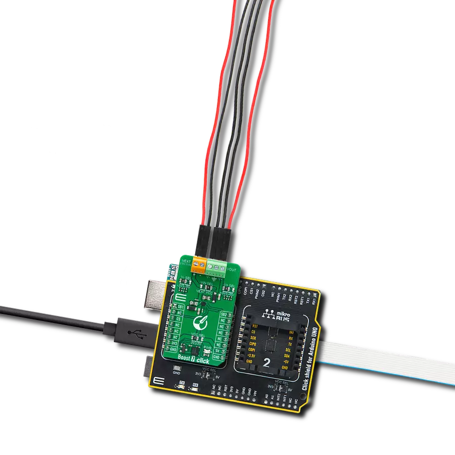
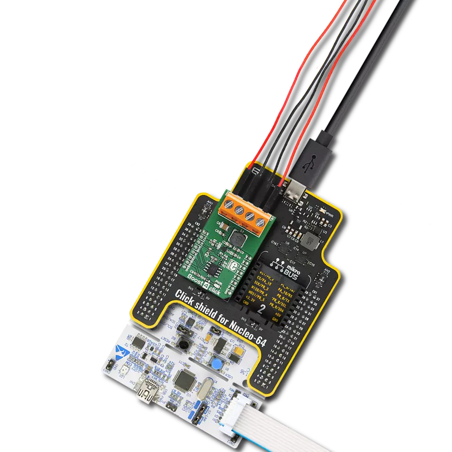
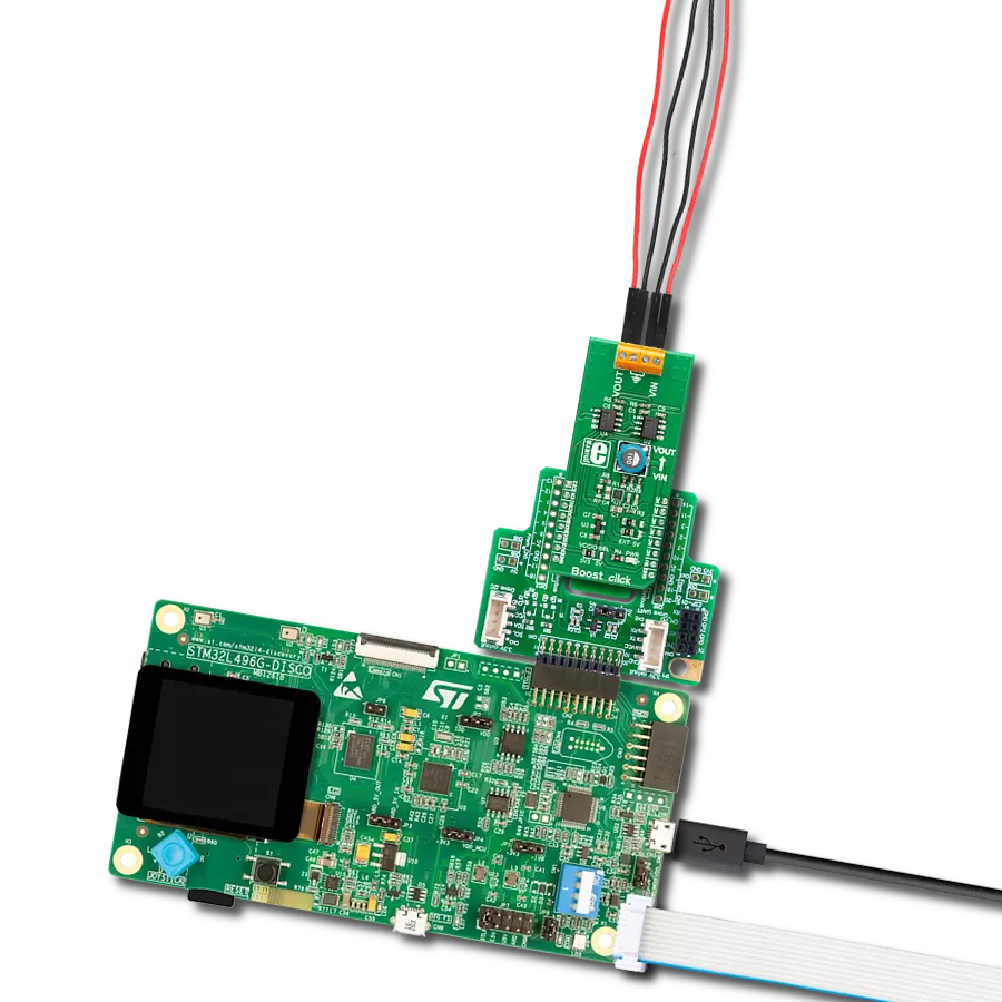
Project assembly

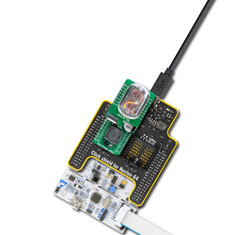
Start by selecting your development board and Click board™. Begin with the Fusion for Tiva v8 as your development board.


Track your results in real time
Application Output
1. Application Output - In Debug mode, the 'Application Output' window enables real-time data monitoring, offering direct insight into execution results. Ensure proper data display by configuring the environment correctly using the provided tutorial.

2. UART Terminal - Use the UART Terminal to monitor data transmission via a USB to UART converter, allowing direct communication between the Click board™ and your development system. Configure the baud rate and other serial settings according to your project's requirements to ensure proper functionality. For step-by-step setup instructions, refer to the provided tutorial.

3. Plot Output - The Plot feature offers a powerful way to visualize real-time sensor data, enabling trend analysis, debugging, and comparison of multiple data points. To set it up correctly, follow the provided tutorial, which includes a step-by-step example of using the Plot feature to display Click board™ readings. To use the Plot feature in your code, use the function: plot(*insert_graph_name*, variable_name);. This is a general format, and it is up to the user to replace 'insert_graph_name' with the actual graph name and 'variable_name' with the parameter to be displayed.

Software Support
Library Description
This library contains API for Step Up Click driver.
Key functions:
stepup_get_percent- This function calculates ouput value in percentstepup_en_set- This function sets the EN pin statestepup_set_out- This function sets output value
Open Source
Code example
The complete application code and a ready-to-use project are available through the NECTO Studio Package Manager for direct installation in the NECTO Studio. The application code can also be found on the MIKROE GitHub account.
/*!
 * \file
 * \brief StepUp Click example
 *
 * # Description
 * This application enables usage of DC-DC step-up (boost) regulator.
 *
 * The demo application is composed of two sections :
 *
 * ## Application Init
 * Initializes SPI driver, sets config word, initializes and configures the device
 *
 * ## Application Task
 * Sets 3 different boost precentage value to device, value changes every 10 seconds.
 *
 * \author MikroE Team
 *
 */
// ------------------------------------------------------------------- INCLUDES

#include "board.h"
#include "log.h"
#include "stepup.h"

// ------------------------------------------------------------------ VARIABLES

static stepup_t stepup;
static log_t logger;

// ------------------------------------------------------ APPLICATION FUNCTIONS

void application_init ( void )
{
    log_cfg_t log_cfg;
    stepup_cfg_t cfg;

    /**
     * Logger initialization.
     * Default baud rate: 115200
     * Default log level: LOG_LEVEL_DEBUG
     * @note If USB_UART_RX and USB_UART_TX
     * are defined as HAL_PIN_NC, you will
     * need to define them manually for log to work.
     * See @b LOG_MAP_USB_UART macro definition for detailed explanation.
     */
    LOG_MAP_USB_UART( log_cfg );
    log_init( &logger, &log_cfg );
    log_info( &logger, "Application Init" );

    //  Click initialization.

    stepup_cfg_setup( &cfg );
    STEPUP_MAP_MIKROBUS( cfg, MIKROBUS_1 );
    stepup_init( &stepup, &cfg );

    stepup_default_cfg( &stepup );

    Delay_ms ( 100 );
    log_info( &logger, "Application Task" );
}

void application_task ( void )
{
    log_info( &logger, "Setting DAC boost to 10%%" );
    stepup_set_percentage( &stepup, 10 );
    // 10 seconds delay
    Delay_ms ( 1000 );
    Delay_ms ( 1000 );
    Delay_ms ( 1000 );
    Delay_ms ( 1000 );
    Delay_ms ( 1000 );
    Delay_ms ( 1000 );
    Delay_ms ( 1000 );
    Delay_ms ( 1000 );
    Delay_ms ( 1000 );
    Delay_ms ( 1000 );

    log_info( &logger, "Setting DAC boost to 60%%" );
    stepup_set_percentage( &stepup, 60 );
    // 10 seconds delay
    Delay_ms ( 1000 );
    Delay_ms ( 1000 );
    Delay_ms ( 1000 );
    Delay_ms ( 1000 );
    Delay_ms ( 1000 );
    Delay_ms ( 1000 );
    Delay_ms ( 1000 );
    Delay_ms ( 1000 );
    Delay_ms ( 1000 );
    Delay_ms ( 1000 );

    log_info( &logger, "Setting DAC boost to 30%%" );
    stepup_set_percentage( &stepup, 30 );
    // 10 seconds delay
    Delay_ms ( 1000 );
    Delay_ms ( 1000 );
    Delay_ms ( 1000 );
    Delay_ms ( 1000 );
    Delay_ms ( 1000 );
    Delay_ms ( 1000 );
    Delay_ms ( 1000 );
    Delay_ms ( 1000 );
    Delay_ms ( 1000 );
    Delay_ms ( 1000 );
}

int main ( void )
{
    /* Do not remove this line or clock might not be set correctly. */
    #ifdef PREINIT_SUPPORTED
    preinit();
    #endif

    application_init( );

    for ( ; ; )
    {
        application_task( );
    }

    return 0;
}


// ------------------------------------------------------------------------ END