Advanced heart monitoring with MCP609 and PIC32MZ2048EFM100
Real-time heart analysis
Published Jul 22, 2025
Click board™
ECG Click
Dev. board
Curiosity PIC32 MZ EF
Compiler
NECTO Studio
MCU
PIC32MZ2048EFM100
Enhance your safety and well-being by providing accurate and reliable information about your heart's electrical activity
A
A
Hardware Overview
How does it work?
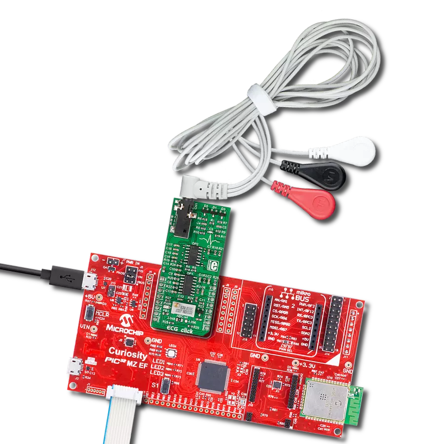
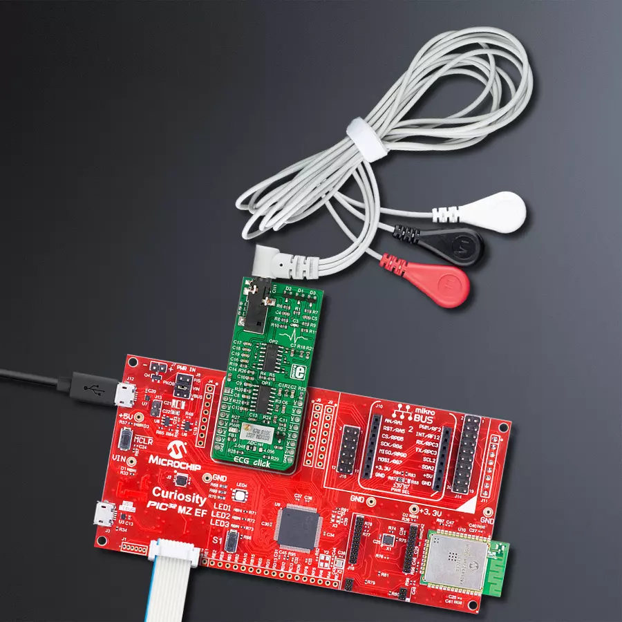
ECG Click is based on two MCP609s, a micropower CMOS operational amplifier from Microchip. These are unity-gain stable, rail-to-rail output swing operational amplifiers with a low offset voltage and input bias current designed to prevent phase reversal when the input pins exceed the supply voltages. ECG Click has a seven-block design. It comprises ESD, overvoltage and overcurrent protection (protecting both the hardware and the user), a pre-amplifier and amplifier, two high-pass filters, a low-pass filter, and a DRL circuit. When the electrical signal from the heart reaches the skin's surface, it becomes significantly faint, measuring only a few millivolts. However, this weak signal faces further obstruction due to muscle activity originating from different body parts. Additionally, electromagnetic interference from the surrounding environment, where the body can act as an antenna, presents another noise source. An onboard 3.5mm phone jack connects cables/electrodes to the Click board™.
The electrode collects voltage from the skin, after which the signal is amplified and filtered and then sent to the analog AN pin of the host MCU over the mikroBUS™ socket. The three electrodes should be placed on the left arm, right arm, and the left side of the abdomen (below the heart), on the left leg. ECG Click has one jumper and a trimmer potentiometer for setting the output voltage to match the input voltage level of the ADC, which will be used (10-bit ADC - 12-bit recommended). As a reference, it uses the MAX6106, a low-cost, micropower, low-dropout, high-output-current voltage reference from Analog Devices. The SMD (0805) jumper determines its output voltage range. When connecting all three electrodes, the output should be a constant voltage (1.024V or 2.048V, depending on the jumper position). The trimmer potentiometer is for adjusting the gain. So, if you set the jumper to the 2.048 position (zero is now 1.024V), the gain will be set so that the ECG
waveform is in the range of 0-2.048V. If you set the jumper to the 4.096 position (zero is now 2.048V), the gain will be set so that the ECG waveform is in the range of 0-4.096V. The final measurement results can be displayed as an Electrocardiogram using a free app, the MikroPlot, a free data visualization tool (Windows). It's a simple tool to help you visualize sensor data recorded over time, suitable for biosignals (ECG, EEG, EMG) and environmental data logging (temperature, humidity, and more). The app can receive data sets from a microcontroller through a USB UART connection. This Click board™ can only be operated with a 5V logic voltage level. The board must perform appropriate logic voltage level conversion before using MCUs with different logic levels. However, the Click board™ comes equipped with a library containing functions and an example code that can be used, as a reference, for further development.

Features overview
Development board
Curiosity PIC32 MZ EF development board is a fully integrated 32-bit development platform featuring the high-performance PIC32MZ EF Series (PIC32MZ2048EFM) that has a 2MB Flash, 512KB RAM, integrated FPU, Crypto accelerator, and excellent connectivity options. It includes an integrated programmer and debugger, requiring no additional hardware. Users can expand
functionality through MIKROE mikroBUS™ Click™ adapter boards, add Ethernet connectivity with the Microchip PHY daughter board, add WiFi connectivity capability using the Microchip expansions boards, and add audio input and output capability with Microchip audio daughter boards. These boards are fully integrated into PIC32’s powerful software framework, MPLAB Harmony,
which provides a flexible and modular interface to application development a rich set of inter-operable software stacks (TCP-IP, USB), and easy-to-use features. The Curiosity PIC32 MZ EF development board offers expansion capabilities making it an excellent choice for a rapid prototyping board in Connectivity, IOT, and general-purpose applications.

Microcontroller Overview
MCU Card / MCU

Architecture
PIC32
MCU Memory (KB)
2048
Silicon Vendor
Microchip
Pin count
100
RAM (Bytes)
524288
You complete me!
Accessories
3-wire ECG/EMG cable comes with a convenient 3.5mm phone jack, and it is designed for electrocardiogram recording. This 1m cable is a practical companion for medical professionals and enthusiasts. To complement this cable, you can also use single-use adhesive ECG/EMG electrodes measuring 48x34mm, each equipped with an ECG/EMG cable stud adapter. These electrodes ensure a seamless experience when paired with our ECG/EMG cable and guarantee reliable ECG/EMG signal transmission for comprehensive cardiac monitoring. Trust in the accuracy and convenience of this setup to effortlessly record electrocardiograms and electromyograms with confidence.

Used MCU Pins
mikroBUS™ mapper
Take a closer look
Click board™ Schematic

Step by step
Project assembly

Start by selecting your development board and Click board™. Begin with the Curiosity PIC32 MZ EF as your development board.


Software Support
Library Description
This library contains API for ECG Click driver.
Key functions:
ecg_generic_read- This function read ADC dataecg_default_cfg- This function executes default configuration for ECG Clickecg_init- This function initializes all necessary pins and peripherals used for ECG Click
Open Source
Code example
The complete application code and a ready-to-use project are available through the NECTO Studio Package Manager for direct installation in the NECTO Studio. The application code can also be found on the MIKROE GitHub account.
/*!
 * \file
 * \brief Ecg Click example
 *
 * # Description
 * This example demonstrates the use of ECG Click board.
 *
 * The demo application is composed of two sections :
 *
 * ## Application Init
 * Initializes Click board.
 *
 * ## Application Task
 * Reads ADC sends results on serial plotter.
 *
 *
 * \author MikroE Team
 *
 */
// ------------------------------------------------------------------- INCLUDES

#include "board.h"
#include "log.h"
#include "ecg.h"

// ------------------------------------------------------------------ VARIABLES

static ecg_t ecg;
static log_t logger;

static uint16_t read_adc;
static uint32_t time_read;

// ------------------------------------------------------- ADDITIONAL FUNCTIONS

void plot_res ( uint16_t plot_data, uint32_t plot_time )
{
    log_printf( &logger, "%u,%u \r\n", plot_data, plot_time);
}

// ------------------------------------------------------ APPLICATION FUNCTIONS

void application_init ( void )
{
    log_cfg_t log_cfg;
    ecg_cfg_t cfg;

    /**
     * Logger initialization.
     * Default baud rate: 115200
     * Default log level: LOG_LEVEL_DEBUG
     * @note If USB_UART_RX and USB_UART_TX
     * are defined as HAL_PIN_NC, you will
     * need to define them manually for log to work.
     * See @b LOG_MAP_USB_UART macro definition for detailed explanation.
     */
    LOG_MAP_USB_UART( log_cfg );
    log_init( &logger, &log_cfg );
    log_info( &logger, "---- Application Init ----" );

    //  Click initialization.

    ecg_cfg_setup( &cfg );
    Delay_ms ( 200 );
    ECG_MAP_MIKROBUS( cfg, MIKROBUS_1 );
    ecg_init( &ecg, &cfg );
    Delay_ms ( 200 );

    time_read = 0;
}

void application_task ( void )
{
    time_read++;
    read_adc = ecg_generic_read( &ecg );
    plot_res( read_adc , time_read);

    Delay_ms ( 5 );
}

int main ( void )
{
    /* Do not remove this line or clock might not be set correctly. */
    #ifdef PREINIT_SUPPORTED
    preinit();
    #endif

    application_init( );

    for ( ; ; )
    {
        application_task( );
    }

    return 0;
}


// ------------------------------------------------------------------------ END
Additional Support
Resources
Category:Biometrics


