Achieve non-contact temperature measurement and thermal imaging using MLX90641 and STM32G071RB
Non-contact temperature measurement and thermal imaging

Published Oct 08, 2024
Click board™
IR Grid 4 Click
Dev. board
Nucleo 64 with STM32G071RB MCU
Compiler
NECTO Studio
MCU
STM32G071RB
Captures and displays thermal images based on temperature variations within the 55° field of view
A
A
Hardware Overview
How does it work?
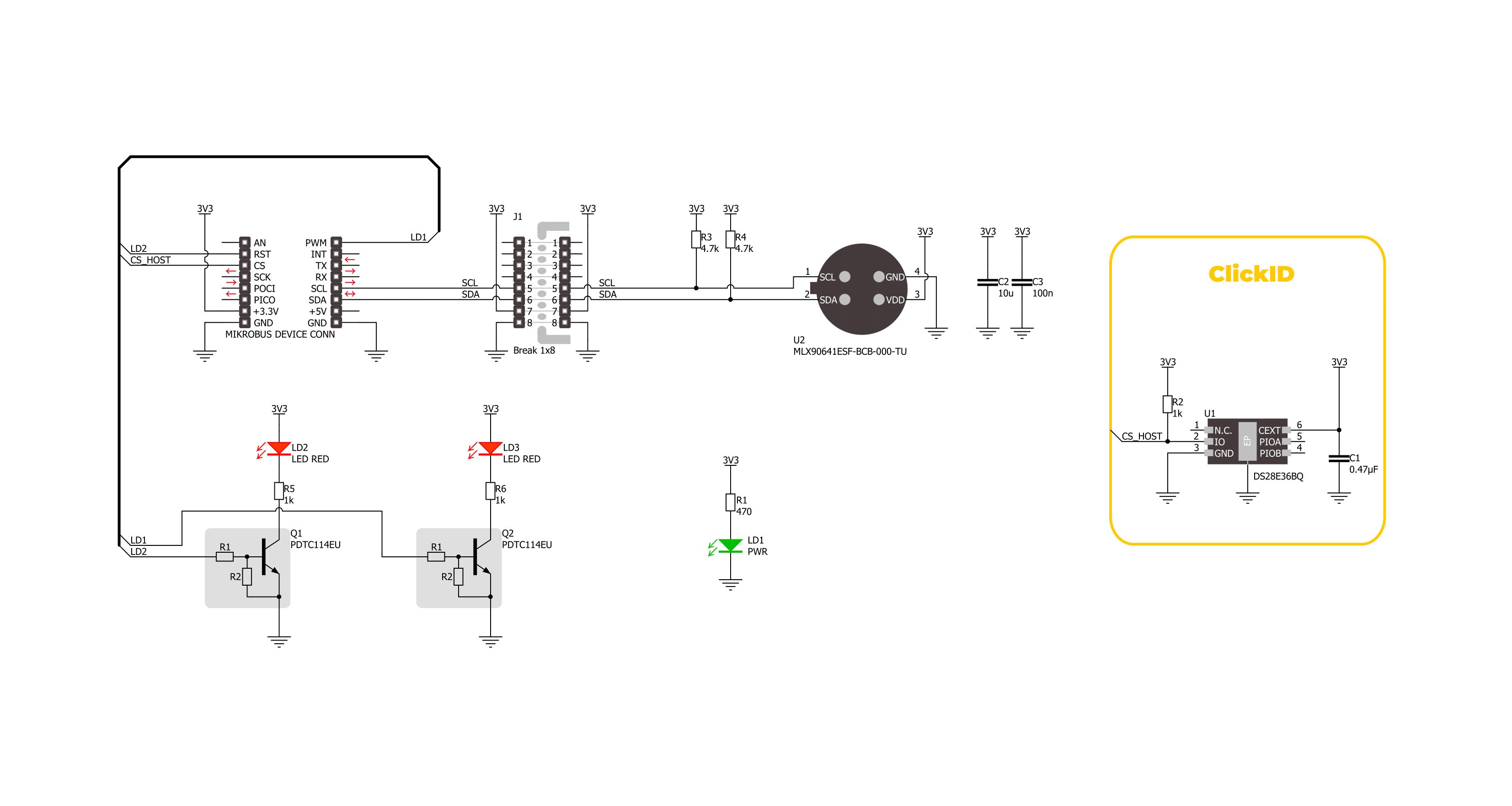
IR Grid 4 Click is based on the MLX90641, a fully calibrated thermal IR array from Melexis in an industry-standard 4-lead TO39 package with a digital interface and a 55° viewing angle. It captures temperature data across a two-dimensional 16x12 matrix (192 pixels) and provides this information as a digital output. It can accurately measure temperatures from -40°C to +300°C and ensures an accuracy of 1°C in typical measurement conditions. With its ability to accurately measure contactless thermal or thermal imaging, IR Grid 4 Click is ideal for high-precision non-contact temperature measurements, intrusion/movement detection, industrial temperature control of moving parts, a visual IR thermometer, and more. This Click board™ is designed in a unique format
supporting the newly introduced MIKROE feature called "Click Snap." Unlike the standardized version of Click boards, this feature allows the main sensor area to become movable by breaking the PCB, opening up many new possibilities for implementation. Thanks to the Snap feature, the MLX90641 can operate autonomously by accessing its signals directly on the pins marked 1-8. Additionally, the Snap part includes a specified and fixed screw hole position, enabling users to secure the Snap board in their desired location. IR Grid 4 Click uses a standard 2-wire I2C interface to communicate with the host MCU, supporting Standard mode with up to 1MHz of frequency clock. In addition to the I2C interface pins, this board also uses two user-configurable pins, LD1 and LD2,
paired with corresponding red LED indicators. These LEDs serve as customizable visual signals, allowing the user to indicate specific operational states of the main sensor, the MLX90641. The LEDs can be programmed to light up under certain conditions, such as when the sensor detects specific temperature thresholds or when it enters a particular mode, providing immediate visual feedback during operation. This Click board™ can be operated only with a 3.3V logic voltage level. The board must perform appropriate logic voltage level conversion before using MCUs with different logic levels. Also, it comes equipped with a library containing functions and an example code that can be used as a reference for further development.

Features overview
Development board
Nucleo-64 with STM32G071RB MCU offers a cost-effective and adaptable platform for developers to explore new ideas and prototype their designs. This board harnesses the versatility of the STM32 microcontroller, enabling users to select the optimal balance of performance and power consumption for their projects. It accommodates the STM32 microcontroller in the LQFP64 package and includes essential components such as a user LED, which doubles as an ARDUINO® signal, alongside user and reset push-buttons, and a 32.768kHz crystal oscillator for precise timing operations. Designed with expansion and flexibility in mind, the Nucleo-64 board features an ARDUINO® Uno V3 expansion connector and ST morpho extension pin
headers, granting complete access to the STM32's I/Os for comprehensive project integration. Power supply options are adaptable, supporting ST-LINK USB VBUS or external power sources, ensuring adaptability in various development environments. The board also has an on-board ST-LINK debugger/programmer with USB re-enumeration capability, simplifying the programming and debugging process. Moreover, the board is designed to simplify advanced development with its external SMPS for efficient Vcore logic supply, support for USB Device full speed or USB SNK/UFP full speed, and built-in cryptographic features, enhancing both the power efficiency and security of projects. Additional connectivity is
provided through dedicated connectors for external SMPS experimentation, a USB connector for the ST-LINK, and a MIPI® debug connector, expanding the possibilities for hardware interfacing and experimentation. Developers will find extensive support through comprehensive free software libraries and examples, courtesy of the STM32Cube MCU Package. This, combined with compatibility with a wide array of Integrated Development Environments (IDEs), including IAR Embedded Workbench®, MDK-ARM, and STM32CubeIDE, ensures a smooth and efficient development experience, allowing users to fully leverage the capabilities of the Nucleo-64 board in their projects.

Microcontroller Overview
MCU Card / MCU

Architecture
ARM Cortex-M0
MCU Memory (KB)
128
Silicon Vendor
STMicroelectronics
Pin count
64
RAM (Bytes)
36864
You complete me!
Accessories
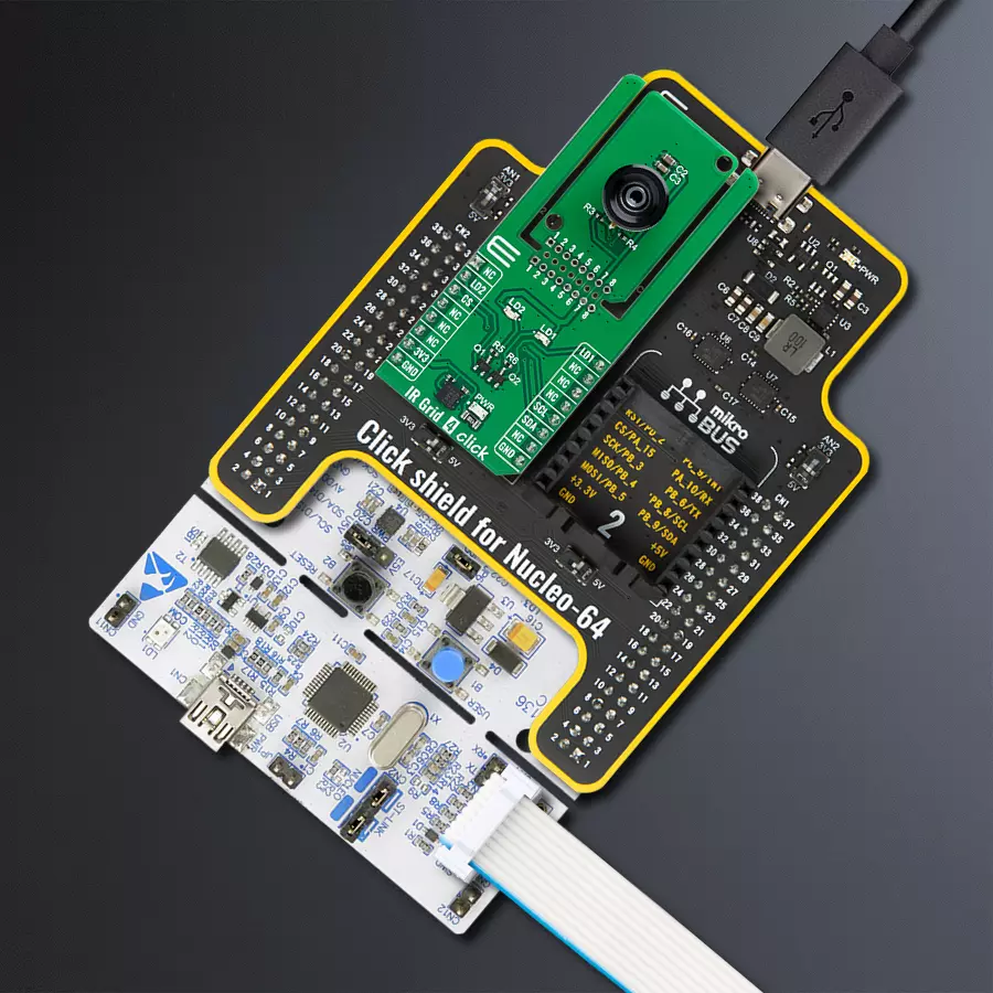
Click Shield for Nucleo-64 comes equipped with two proprietary mikroBUS™ sockets, allowing all the Click board™ devices to be interfaced with the STM32 Nucleo-64 board with no effort. This way, Mikroe allows its users to add any functionality from our ever-growing range of Click boards™, such as WiFi, GSM, GPS, Bluetooth, ZigBee, environmental sensors, LEDs, speech recognition, motor control, movement sensors, and many more. More than 1537 Click boards™, which can be stacked and integrated, are at your disposal. The STM32 Nucleo-64 boards are based on the microcontrollers in 64-pin packages, a 32-bit MCU with an ARM Cortex M4 processor operating at 84MHz, 512Kb Flash, and 96KB SRAM, divided into two regions where the top section represents the ST-Link/V2 debugger and programmer while the bottom section of the board is an actual development board. These boards are controlled and powered conveniently through a USB connection to program and efficiently debug the Nucleo-64 board out of the box, with an additional USB cable connected to the USB mini port on the board. Most of the STM32 microcontroller pins are brought to the IO pins on the left and right edge of the board, which are then connected to two existing mikroBUS™ sockets. This Click Shield also has several switches that perform functions such as selecting the logic levels of analog signals on mikroBUS™ sockets and selecting logic voltage levels of the mikroBUS™ sockets themselves. Besides, the user is offered the possibility of using any Click board™ with the help of existing bidirectional level-shifting voltage translators, regardless of whether the Click board™ operates at a 3.3V or 5V logic voltage level. Once you connect the STM32 Nucleo-64 board with our Click Shield for Nucleo-64, you can access hundreds of Click boards™, working with 3.3V or 5V logic voltage levels.

Used MCU Pins
mikroBUS™ mapper
Take a closer look
Click board™ Schematic
Step by step
Project assembly
Start by selecting your development board and Click board™. Begin with the Nucleo 64 with STM32G071RB MCU as your development board.


Software Support
Library Description
This library contains API for IR Grid 4 Click driver.
Key functions:
irgrid4_get_measurement- This function reads the RAM frame data and calculates ambient temperature and a 16x12 IR grid object temperature.irgrid4_set_refresh_rate- This function sets the IR data refresh rate.irgrid4_enable_led1- This function enables the LED1.
Open Source
Code example
The complete application code and a ready-to-use project are available through the NECTO Studio Package Manager for direct installation in the NECTO Studio. The application code can also be found on the MIKROE GitHub account.
/*!
 * @file main.c
 * @brief IR Grid 4 Click example
 *
 * # Description
 * This example demonstrates the use of IR Grid 4 Click by reading and displaying
 * the ambient and object temperature measurements in a 16x12 pixels grid format.
 *
 * The demo application is composed of two sections :
 *
 * ## Application Init
 * Initializes the driver and performs the Click default configuration.
 *
 * ## Application Task
 * Reads the ambient and object temperature measurements every 500ms and displays
 * the results on the USB UART in a form of a 16x12 pixels grid.
 *
 * @author Stefan Filipovic
 *
 */

#include "board.h"
#include "log.h"
#include "irgrid4.h"

static irgrid4_t irgrid4;
static log_t logger;

void application_init ( void )
{
    log_cfg_t log_cfg;  /**< Logger config object. */
    irgrid4_cfg_t irgrid4_cfg;  /**< Click config object. */

    /**
     * Logger initialization.
     * Default baud rate: 115200
     * Default log level: LOG_LEVEL_DEBUG
     * @note If USB_UART_RX and USB_UART_TX
     * are defined as HAL_PIN_NC, you will
     * need to define them manually for log to work.
     * See @b LOG_MAP_USB_UART macro definition for detailed explanation.
     */
    LOG_MAP_USB_UART( log_cfg );
    log_init( &logger, &log_cfg );
    log_info( &logger, " Application Init " );

    // Click initialization.
    irgrid4_cfg_setup( &irgrid4_cfg );
    IRGRID4_MAP_MIKROBUS( irgrid4_cfg, MIKROBUS_1 );
    if ( I2C_MASTER_ERROR == irgrid4_init( &irgrid4, &irgrid4_cfg ) )
    {
        log_error( &logger, " Communication init." );
        for ( ; ; );
    }

    if ( IRGRID4_ERROR == irgrid4_default_cfg ( &irgrid4 ) )
    {
        log_error( &logger, " Default configuration." );
        for ( ; ; );
    }

    log_info( &logger, " Application Task " );
}

void application_task ( void )
{
    float image[ 192 ] = { 0 };
    float ambient_temp = 0;
    if ( IRGRID4_OK == irgrid4_get_measurement ( &irgrid4, &ambient_temp, image ) )
    {
        log_printf( &logger, " Ambient temperature: %.2f degC\r\n", ambient_temp );
        log_printf( &logger, "--- Object temperature image ---\r\n" );
        for ( uint8_t pixel_cnt = 0; pixel_cnt < 192; pixel_cnt++ )
        {
            log_printf( &logger, "%.2f", image[ pixel_cnt ] );
            if ( 15 == ( pixel_cnt % 16 ) )
            {
                log_printf( &logger, "\r\n" );
            }
            else
            {
                log_printf( &logger, " | " );
            }
        }
        log_printf( &logger, "--------------------------------\r\n" );
    }
}

int main ( void )
{
    /* Do not remove this line or clock might not be set correctly. */
    #ifdef PREINIT_SUPPORTED
    preinit();
    #endif

    application_init( );

    for ( ; ; )
    {
        application_task( );
    }

    return 0;
}

// ------------------------------------------------------------------------ END
Additional Support
Resources
Category:Temperature & humidity


