Elevate your temperature monitoring game with MCP9800 and STM32F103RB
Heat up your efficiency

Published Oct 08, 2024
Click board™
Thermo 7 Click
Dev. board
Nucleo 64 with STM32F103RB MCU
Compiler
NECTO Studio
MCU
STM32F103RB
Unlock the power of temperature data with our solution, enabling data-driven decisions that drive your success
A
A
Hardware Overview
How does it work?
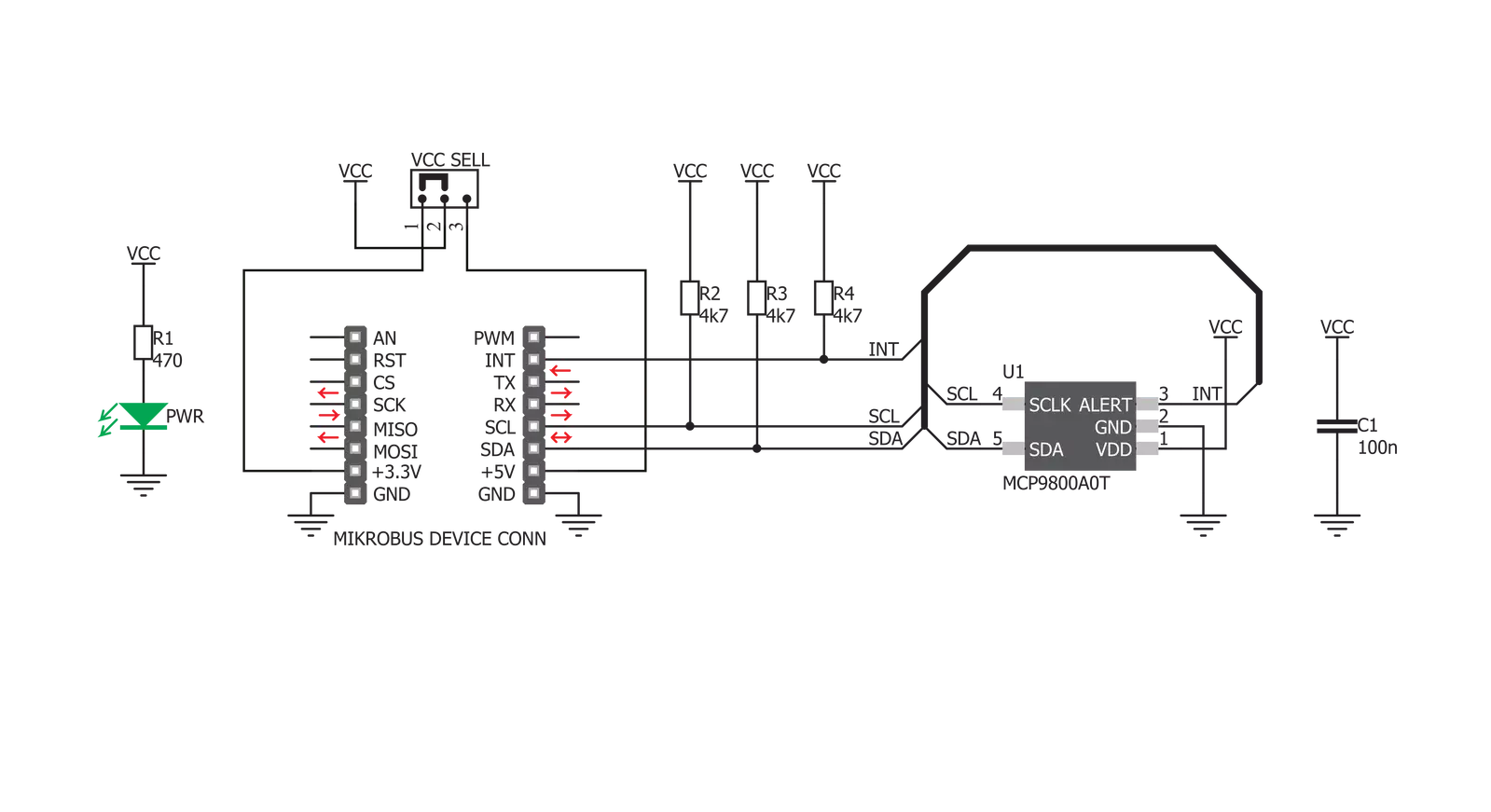
Thermo 7 Click is based on the MCP9800, a high-accuracy temperature sensor IC with the 2-Wire interface, from Microchip. The Click board™ itself has a reasonably small number of components because most of the measurement circuitry is already integrated on the MCP9800 sensor. The I2C / SMBus compatible serial interface lines, along with the ALERT pin, which also works in the open drain configuration, are pulled up by the onboard resistors. The 2-Wire lines are routed to the respective I2C lines of the mikroBUS™ (SCK and SDA), while the ALERT pin is routed to the INT pin of the mikroBUS™. The sensor IC uses the I2C/SMBus compatible communication interface. There are four registers, used to set the temperature limit, temperature hysteresis for the interrupt events, configuration register used to store all the working parameters, and the read-only register which holds the sampled temperature data. More information about all the registers can be found in the MCP9800 datasheet. However, provided library contains functions that simplify the use of the Thermo 7 click. The included application example demonstrates their functionality and it can be used as a reference for custom design. An analog signal from the thermal sensor is sampled by the sigma-delta ADC converter, with the selectable resolution of 9, 10, 11 and 12 bits. The sampling resolution affects the temperature step sizes, as well as the time
required to complete the conversion. The step sizes vary between the 0.5°C with 30ms of conversion time for 9bit sampling, and 0.0625°C with 240ms of conversion time for 12bit resolution. The selectable resolution allows a compromise to be made between the resolution and the conversion time, depending on the application requirements. The ALERT pin is used to trigger an interrupt event on the host MCU. This pin has a programmable polarity: it can be set to be asserted either to a HIGH logic level or to a LOW logic level. Since the Click board™ features a pull-up resistor, it is advised to set the polarity so that the asserted state drives the pin to a LOW logic level. A special mechanism is employed to reduce false ALERT triggering. This mechanism includes queueing of the cycles in which the temperature limit is exceeded. As already described, the ALERT pin is routed to the INT pin of the mikroBUS™. The ALERT pin can be set to work in two different modes: Comparator mode and Interrupt mode. When working in the Comparator mode, this pin will be triggered whenever a temperature limit is exceeded. The ALERT pin stays asserted until the temperature drops below the hysteresis level. Both values are set in the respective temperature registers (limit and hysteresis). This mode is useful for thermostat-like applications: it can be used to power down a system in case of overheating or turn off the cooling fan if the temperature is low
enough. If set to work in the Interrupt mode, the ALERT pin will stay asserted after exceeding the temperature limit, until any internal register is read. When the temperature drops below the hysteresis level, the ALERT pin will be asserted again, waiting for the internal registers to be read once again. This mode is used to trigger an interrupt on the host MCU, which is supposed to read the sensor when the interrupt event is generated. The device can be set to work in several different power modes. It can be set to continuously sample the temperature measurements, it can be set to work in the one-shot mode, and it can be set to stay in the shutdown mode. The shutdown mode consumes the least power, keeping all the internal sections but the communication section, unpowered. The one-shot mode allows the device to stay in the shutdown mode, run a single conversion cycle on demand, and the revert back to the shutdown mode. This allows for a lower power consumption. The design of the Click board™ itself is such that the thermal radiation from other components, which might affect the environmental temperature readings of the sensor, is reduced. The onboard SMD jumper labeled as VCC SEL allows voltage selection for interfacing with both 3.3V and 5V MCUs.

Features overview
Development board
Nucleo-64 with STM32F103RB MCU offers a cost-effective and adaptable platform for developers to explore new ideas and prototype their designs. This board harnesses the versatility of the STM32 microcontroller, enabling users to select the optimal balance of performance and power consumption for their projects. It accommodates the STM32 microcontroller in the LQFP64 package and includes essential components such as a user LED, which doubles as an ARDUINO® signal, alongside user and reset push-buttons, and a 32.768kHz crystal oscillator for precise timing operations. Designed with expansion and flexibility in mind, the Nucleo-64 board features an ARDUINO® Uno V3 expansion connector and ST morpho extension pin
headers, granting complete access to the STM32's I/Os for comprehensive project integration. Power supply options are adaptable, supporting ST-LINK USB VBUS or external power sources, ensuring adaptability in various development environments. The board also has an on-board ST-LINK debugger/programmer with USB re-enumeration capability, simplifying the programming and debugging process. Moreover, the board is designed to simplify advanced development with its external SMPS for efficient Vcore logic supply, support for USB Device full speed or USB SNK/UFP full speed, and built-in cryptographic features, enhancing both the power efficiency and security of projects. Additional connectivity is
provided through dedicated connectors for external SMPS experimentation, a USB connector for the ST-LINK, and a MIPI® debug connector, expanding the possibilities for hardware interfacing and experimentation. Developers will find extensive support through comprehensive free software libraries and examples, courtesy of the STM32Cube MCU Package. This, combined with compatibility with a wide array of Integrated Development Environments (IDEs), including IAR Embedded Workbench®, MDK-ARM, and STM32CubeIDE, ensures a smooth and efficient development experience, allowing users to fully leverage the capabilities of the Nucleo-64 board in their projects.

Microcontroller Overview
MCU Card / MCU

Architecture
ARM Cortex-M3
MCU Memory (KB)
128
Silicon Vendor
STMicroelectronics
Pin count
64
RAM (Bytes)
20480
You complete me!
Accessories
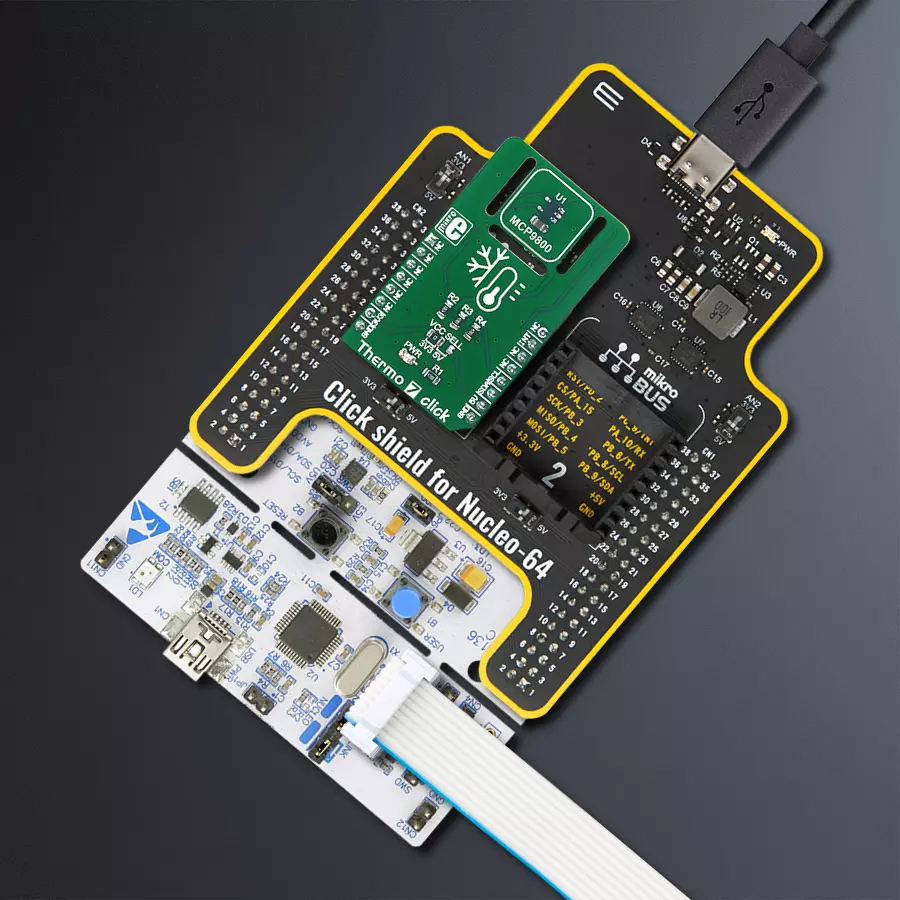
Click Shield for Nucleo-64 comes equipped with two proprietary mikroBUS™ sockets, allowing all the Click board™ devices to be interfaced with the STM32 Nucleo-64 board with no effort. This way, Mikroe allows its users to add any functionality from our ever-growing range of Click boards™, such as WiFi, GSM, GPS, Bluetooth, ZigBee, environmental sensors, LEDs, speech recognition, motor control, movement sensors, and many more. More than 1537 Click boards™, which can be stacked and integrated, are at your disposal. The STM32 Nucleo-64 boards are based on the microcontrollers in 64-pin packages, a 32-bit MCU with an ARM Cortex M4 processor operating at 84MHz, 512Kb Flash, and 96KB SRAM, divided into two regions where the top section represents the ST-Link/V2 debugger and programmer while the bottom section of the board is an actual development board. These boards are controlled and powered conveniently through a USB connection to program and efficiently debug the Nucleo-64 board out of the box, with an additional USB cable connected to the USB mini port on the board. Most of the STM32 microcontroller pins are brought to the IO pins on the left and right edge of the board, which are then connected to two existing mikroBUS™ sockets. This Click Shield also has several switches that perform functions such as selecting the logic levels of analog signals on mikroBUS™ sockets and selecting logic voltage levels of the mikroBUS™ sockets themselves. Besides, the user is offered the possibility of using any Click board™ with the help of existing bidirectional level-shifting voltage translators, regardless of whether the Click board™ operates at a 3.3V or 5V logic voltage level. Once you connect the STM32 Nucleo-64 board with our Click Shield for Nucleo-64, you can access hundreds of Click boards™, working with 3.3V or 5V logic voltage levels.

Used MCU Pins
mikroBUS™ mapper
Take a closer look
Click board™ Schematic
Step by step
Project assembly
Start by selecting your development board and Click board™. Begin with the Nucleo 64 with STM32F103RB MCU as your development board.


Software Support
Library Description
This library contains API for Thermo 7 Click driver.
Key functions:
thermo7_get_hysteresis_temperature- This fuction gets Hysteresis Temperature.thermo7_set_limit_temperature- This fuction sets limit temperature.thermo7_get_interrupt- This fuction reads state of interrupt pins.
Open Source
Code example
The complete application code and a ready-to-use project are available through the NECTO Studio Package Manager for direct installation in the NECTO Studio. The application code can also be found on the MIKROE GitHub account.
/*!
 * \file
 * \brief Thermo7 Click example
 *
 * # Description
 * This application reads ambient temperature.
 *
 * The demo application is composed of two sections :
 *
 * ## Application Init
 * Initializes device.
 *
 * ## Application Task
 * Reads ambient temperature and logs to USBUART every 1 seconds.
 *
 * \author MikroE Team
 *
 */
// ------------------------------------------------------------------- INCLUDES

#include "board.h"
#include "log.h"
#include "thermo7.h"

// ------------------------------------------------------------------ VARIABLES

static thermo7_t thermo7;
static log_t logger;

// ------------------------------------------------------ APPLICATION FUNCTIONS

void application_init ( void )
{
    log_cfg_t log_cfg;
    thermo7_cfg_t cfg;

    /**
     * Logger initialization.
     * Default baud rate: 115200
     * Default log level: LOG_LEVEL_DEBUG
     * @note If USB_UART_RX and USB_UART_TX
     * are defined as HAL_PIN_NC, you will
     * need to define them manually for log to work.
     * See @b LOG_MAP_USB_UART macro definition for detailed explanation.
     */
    LOG_MAP_USB_UART( log_cfg );
    log_init( &logger, &log_cfg );
    log_info( &logger, "---- Application Init ----" );

    //  Click initialization.

    thermo7_cfg_setup( &cfg );
    THERMO7_MAP_MIKROBUS( cfg, MIKROBUS_1 );
    thermo7_init( &thermo7, &cfg );

    thermo7_set_configuration( &thermo7, THERMO7_CONFIG_COMPARATOR_MODE | THERMO7_CONFIG_ALERT_POLARITY_ACTIVE_HIGH );
    thermo7_set_resolution( &thermo7, THERMO7_CONFIG_ADC_RESOLUTION_12bit );
}

void application_task ( void )
{
    float ambient_temperature;

    ambient_temperature = thermo7_read_ambient_temperature( &thermo7 );
    log_printf( &logger, " Ambient temperature : %f C\r\n", ambient_temperature
);

    Delay_ms ( 1000 );
}

int main ( void )
{
    /* Do not remove this line or clock might not be set correctly. */
    #ifdef PREINIT_SUPPORTED
    preinit();
    #endif

    application_init( );

    for ( ; ; )
    {
        application_task( );
    }

    return 0;
}

// ------------------------------------------------------------------------ END
Additional Support
Resources
Category:Temperature & humidity


