Experience the future of temperature record-keeping with MAX6642 and ATmega328P
We keep your temperature wisdom stored safely

Published Feb 14, 2024
Click board™
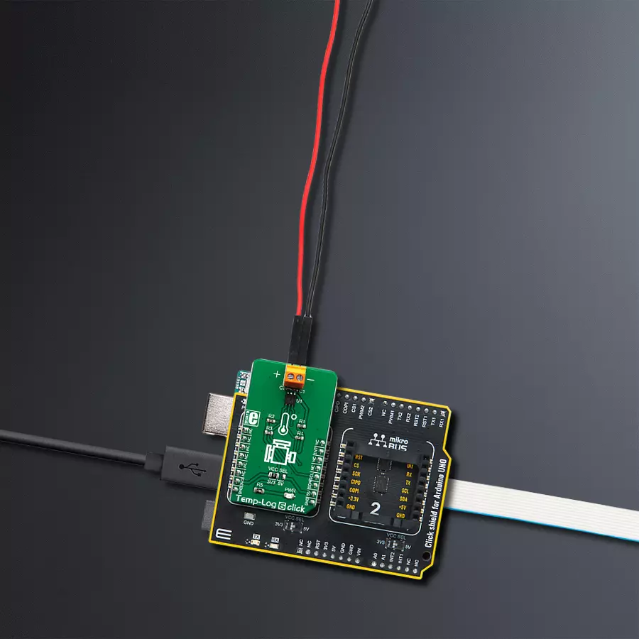
Temp-Log 6 Click
Dev. board
Arduino UNO Rev3
Compiler
NECTO Studio
MCU
ATmega328P
Elevate your temperature monitoring game with our solution's advanced EEPROM memory, ensuring you have the data you need when you need it.
A
A
Hardware Overview
How does it work?
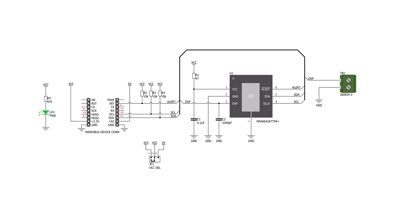
Temp-Log 6 Click is based on the MAX6642, a ±1°C, SMBus/I2C compatible local/remote temperature sensor with an overtemperature alarm, from Analog Devices. This sensor is capable of measuring its own die temperature, as well as a temperature of a remote PN junction, which can be either a PNP transistor on a substrate of some integrated component (typically CPU, FPGA, ASIC or GPU), but also a discrete diode-connected PNP transistor with its collector grounded. There are some specific requirements for a discrete component when using it as a remote temperature sensor: it has to be a small signal PNP transistor with its collector grounded along with its base, while the emitter is connected to the DXP input pin of the MAX6642. Datasheet of the MAX6642 also states some forward voltage ranges for the highest and the lowest expected temperatures, so the transistor should be selected according to these parameters. The discrete component can be connected to the screw terminal at the edge of the Click board™. The MAX6642 features a 10-bit ADC
which results in having the 0.25°C resolution. For the local temperature sensing, there are only 8 bits of data available, while the full 10-bit resolution is used for the remote sensing. The MAX6642 IC automatically sends biasing current through the PN junctions, while the IC samples the forward voltage for the given current and calculates the temperature. The ADC integrates the result over a period of 60ms, reducing the noise that way. Therefore, the temperature acquisition is not particularly fast. In return, the temperature measurement results are more accurate and reliable. The accuracy of the remote measurement depends on the ideality factor of the remote PN junction. The ideality factor is one of the listed specifications of devices equipped with such on-chip elements. The MAX6642 is designed for an ideality factor of 1.008, a typical value for the Intel Pentium III CPU. However, if using IC with a different ideality factor, a conversion formula needs to be applied. The conversion formula can be found within the MAX6642 datasheet. The MAX6642 IC also features the ALERT reporting
capability. If a programmed threshold is exceeded, the ALERT pin will be asserted to a LOW logic level. When the ALERT pin is asserted, it will remain latched until its STATUS register is read after the overtemperature condition no longer exists. Another way to clear the ALERT interrupt is to respond to the alert response address. This is a global I2C/SMBus protocol, where the host MCU broadcasts a Receive Byte transmission after the interrupt is received. One (or more) slave devices which generated this interrupt will respond, sending their I2C slave address, following the bus arbitration rules. This protocol is explained in more details within the MAX6642 datasheet. The ALERT pin is routed to the INT pin of the mikroBUS™ and it is pulled up by a resistor. Temp-Log 6 click uses an I2C interface to communicate with the host MCU. It is equipped with an SMD jumper labeled as VCC SEL. This jumper is used to select the power supply for the pull-up resistors on the I2C bus, allowing both 3.3V and 5V MCUs to be interfaced with this Click board™.

Features overview
Development board
Arduino UNO is a versatile microcontroller board built around the ATmega328P chip. It offers extensive connectivity options for various projects, featuring 14 digital input/output pins, six of which are PWM-capable, along with six analog inputs. Its core components include a 16MHz ceramic resonator, a USB connection, a power jack, an
ICSP header, and a reset button, providing everything necessary to power and program the board. The Uno is ready to go, whether connected to a computer via USB or powered by an AC-to-DC adapter or battery. As the first USB Arduino board, it serves as the benchmark for the Arduino platform, with "Uno" symbolizing its status as the
first in a series. This name choice, meaning "one" in Italian, commemorates the launch of Arduino Software (IDE) 1.0. Initially introduced alongside version 1.0 of the Arduino Software (IDE), the Uno has since become the foundational model for subsequent Arduino releases, embodying the platform's evolution.

Microcontroller Overview
MCU Card / MCU

Architecture
AVR
MCU Memory (KB)
32
Silicon Vendor
Microchip
Pin count
28
RAM (Bytes)
2048
You complete me!
Accessories
Click Shield for Arduino UNO has two proprietary mikroBUS™ sockets, allowing all the Click board™ devices to be interfaced with the Arduino UNO board without effort. The Arduino Uno, a microcontroller board based on the ATmega328P, provides an affordable and flexible way for users to try out new concepts and build prototypes with the ATmega328P microcontroller from various combinations of performance, power consumption, and features. The Arduino Uno has 14 digital input/output pins (of which six can be used as PWM outputs), six analog inputs, a 16 MHz ceramic resonator (CSTCE16M0V53-R0), a USB connection, a power jack, an ICSP header, and reset button. Most of the ATmega328P microcontroller pins are brought to the IO pins on the left and right edge of the board, which are then connected to two existing mikroBUS™ sockets. This Click Shield also has several switches that perform functions such as selecting the logic levels of analog signals on mikroBUS™ sockets and selecting logic voltage levels of the mikroBUS™ sockets themselves. Besides, the user is offered the possibility of using any Click board™ with the help of existing bidirectional level-shifting voltage translators, regardless of whether the Click board™ operates at a 3.3V or 5V logic voltage level. Once you connect the Arduino UNO board with our Click Shield for Arduino UNO, you can access hundreds of Click boards™, working with 3.3V or 5V logic voltage levels.

Used MCU Pins
mikroBUS™ mapper
Take a closer look
Click board™ Schematic
Step by step
Project assembly

Start by selecting your development board and Click board™. Begin with the Arduino UNO Rev3 as your development board.


Software Support
Library Description
This library contains API for Temp-Log 6 Click driver.
Key functions:
templog6_write_byte- Writes one byte of data.templog6_read_byte- Reads one byte of data.templog6_get_interrupt- Gets the INT pin.
Open Source
Code example
The complete application code and a ready-to-use project are available through the NECTO Studio Package Manager for direct installation in the NECTO Studio. The application code can also be found on the MIKROE GitHub account.
/*!
 * \file
 * \brief TempLog6 Click example
 *
 * # Description
 * The example starts off with the initialization and configuration of the Click and logger
 * modules, tests the communication channel and reads and displays local and remote temperature
 * values every second.
 *
 * The demo application is composed of two sections :
 *
 * ## Application Init
 * Initializes and configures the Click and logger modules and tests the communication for errors.
 *
 * ## Application Task
 * Reads and displays local and remote temperature values every second.
 *
 * \author MikroE Team
 *
 */
// ------------------------------------------------------------------- INCLUDES

#include "board.h"
#include "log.h"
#include "templog6.h"

// ------------------------------------------------------------------ VARIABLES

static templog6_t templog6;
static log_t logger;

// ------------------------------------------------------ APPLICATION FUNCTIONS

void application_init ( )
{
    log_cfg_t log_cfg;
    templog6_cfg_t cfg;

    uint8_t test;

    /**
     * Logger initialization.
     * Default baud rate: 115200
     * Default log level: LOG_LEVEL_DEBUG
     * @note If USB_UART_RX and USB_UART_TX
     * are defined as HAL_PIN_NC, you will
     * need to define them manually for log to work.
     * See @b LOG_MAP_USB_UART macro definition for detailed explanation.
     */
    LOG_MAP_USB_UART( log_cfg );
    log_init( &logger, &log_cfg );
    log_info( &logger, "---- Application Init ----" );

    //  Click initialization.

    templog6_cfg_setup( &cfg );
    TEMPLOG6_MAP_MIKROBUS( cfg, MIKROBUS_1 );
    templog6_init( &templog6, &cfg );

    // Test communication

    test = templog6_read_byte( &templog6, TEMPLOG6_REG_MANUFACTURER_ID );

    if ( test == TEMPLOG6_MANUFACTURER_ID )
    {
        log_printf( &logger, "--- Comunication OK!!! ---\r\n" );
    }
    else
    {
        log_printf( &logger, "--- Comunication ERROR!!! ---\r\n" );
        for ( ; ; );
    }

    templog6_default_cfg( &templog6 );

    log_printf( &logger, "--- Start measurement ---\r\n" );
}

void application_task ( )
{
    float remote_temp;
    float local_temp;

    local_temp = templog6_read_byte( &templog6, TEMPLOG6_REG_LOCAL_TEMPERATURE );
    log_printf( &logger, "--- Local Temperature: %f C\r\n", local_temp );

    remote_temp = templog6_read_byte( &templog6, TEMPLOG6_REG_REMOTE_TEMPERATURE );
    log_printf( &logger, "--- Remote Temperature: %f C\r\n", remote_temp );

    log_printf( &logger, "-----------------------------\r\n" );
    Delay_ms ( 1000 );
}

int main ( void )
{
    /* Do not remove this line or clock might not be set correctly. */
    #ifdef PREINIT_SUPPORTED
    preinit();
    #endif

    application_init( );

    for ( ; ; )
    {
        application_task( );
    }

    return 0;
}

// ------------------------------------------------------------------------ END
Additional Support
Resources
Category:Temperature & humidity


