Achieve ideal conditions for your activities with MCP9808 and PIC32MZ2048EFM100
Your climate, your control – know your surroundings

Published Nov 07, 2023
Click board™
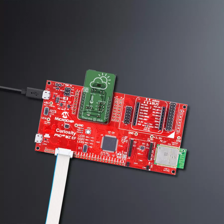
Thermo 8 Click
Dev. board
Curiosity PIC32 MZ EF
Compiler
NECTO Studio
MCU
PIC32MZ2048EFM100
Our temperature measurement solution offers precision beyond measure, ensuring your processes run smoothly and efficiently.
A
A
Hardware Overview
How does it work?
Thermo 8 Click is based on the MCP9808, a digital temperature sensor with ±0.5 °C maximum accuracy, from Microchip. The MCP9808 uses a bandgap type temperature sensor, which is converted by a delta-sigma A/D converter to a digital value, available via the I2C interface. The user has the ability to select the resolution of the measurement, ranging from ±0.5°C, down to ±0.0625°C. The resolution is determined by the internal sample averaging. Therefore, a higher resolution results in longer conversion times. For example, the conversion time for the resolution of ±0.0625 °C is 250ms, while the conversion time for the resolution of ±0.5 °C is only 30ms. The temperature is stored to an output register after the conversion is done. This register is double-buffered, which means that the new data can be written in the background, while the host microcontroller (MCU) performs a reading of the current value. The thermal data is stored as a 13-bit value, in 2's complement format. Along with the thermal data, this register also contains bits that indicate a thermal alert condition. There are three possible alert conditions. The extensive alerting engine is one of the key features of the MCP9808.
The ALERT pin of the MCP9808 is routed to the INT pin of the mikroBUS™, which is labeled as ALE on this Click board™. It can be programmed to be asserted to a HIGH
or to a LOW logic level. However, the Click board™ uses the pull-up resistor to predetermine its idle state to a logic HIGH level. Depending on the application, this pin can be set to operate as a typical interrupt pin, or as a comparator. When set to operate as the interrupt, this pin will be latched until the host MCU sets the Interrupt Clear bit (bit 5 of the CONFIG register, more information in the MCP9808 datasheet). When set to operate as the comparator, the ALERT pin will be asserted only while the alert condition exists. As soon as the temperature falls within the programmed limits, the pin will be de-asserted. While the interrupt mode is useful when an MCU is used to control some process, having to acknowledge the action, the comparator mode can be used to directly control a device, such as a cooling fan in electronic equipment, or PC peripheral. The alert thresholds can be programmed by the user. There are dedicated registers, where the user can enter the threshold value, along with the sign. The value should be entered in 2's complement format. There is also a dedicated register where the thermal hysteresis can be entered, reducing the probability of false reporting when the temperature drifts near the threshold value. The hysteresis can be set in the range from 0 °C up to +6 °C, in four discrete steps. Besides the threshold registers,
there is another register which contains the value used to trigger a special alert mode: the critical temperature mode. This mode will force the device to work in the comparator mode, as long as the critical temperature condition exists. The same hysteresis value is applied to this threshold, reducing the probability of false reports. For more details about the alert modes, please refer to the datasheet of the MCP9808s. However, the Click board™ comes with the mikroSDK compliant library of functions, which simplify the firmware development by encapsulating all the conversion and initialization routines required by the MCP9808 IC. The MCP9808 also supports a SHUTDOWN mode, which reduces the power consumption by turning off the sensor. However, the last conversion is still available in the output register. Even the alert pin state remains unaffected when the SHUTDOWN mode is engaged. The I2C slave address of the device can be selected by switching a group of SMD jumpers, labeled as ADDR SEL. Each jumper will set the appropriate LSB of the device to either logic 0 or logic 1, determining the final I2C slave address. The power supply voltage can also be set by an SMD jumper labeled as VCC SEL, between 3.3V and 5V. This will also set the logic voltage level of the Click board™.

Features overview
Development board
Curiosity PIC32 MZ EF development board is a fully integrated 32-bit development platform featuring the high-performance PIC32MZ EF Series (PIC32MZ2048EFM) that has a 2MB Flash, 512KB RAM, integrated FPU, Crypto accelerator, and excellent connectivity options. It includes an integrated programmer and debugger, requiring no additional hardware. Users can expand
functionality through MIKROE mikroBUS™ Click™ adapter boards, add Ethernet connectivity with the Microchip PHY daughter board, add WiFi connectivity capability using the Microchip expansions boards, and add audio input and output capability with Microchip audio daughter boards. These boards are fully integrated into PIC32’s powerful software framework, MPLAB Harmony,
which provides a flexible and modular interface to application development a rich set of inter-operable software stacks (TCP-IP, USB), and easy-to-use features. The Curiosity PIC32 MZ EF development board offers expansion capabilities making it an excellent choice for a rapid prototyping board in Connectivity, IOT, and general-purpose applications.

Microcontroller Overview
MCU Card / MCU

Architecture
PIC32
MCU Memory (KB)
2048
Silicon Vendor
Microchip
Pin count
100
RAM (Bytes)
524288
Used MCU Pins
mikroBUS™ mapper
Take a closer look
Click board™ Schematic

Step by step
Project assembly

Start by selecting your development board and Click board™. Begin with the Curiosity PIC32 MZ EF as your development board.


Software Support
Library Description
This library contains API for Thermo 8 Click driver.
Key functions:
thermo8_get_temperature- This function returns the temperature value is deg Cthermo8_set_resolution- This function sets the conversion resoult temperature step depending on the passed constant.thermo8_limit_set-This function setting the temperature alarm levels for the lower, upper and critical alert levels.
Open Source
Code example
The complete application code and a ready-to-use project are available through the NECTO Studio Package Manager for direct installation in the NECTO Studio. The application code can also be found on the MIKROE GitHub account.
/*!
 * \file
 * \brief Thermo8 Click example
 *
 * # Description
 * This application measures temperature.
 *
 * The demo application is composed of two sections :
 *
 * ## Application Init
 * Initialize device.
 *
 * ## Application Task
 * Wait for the interrupt pin to be triggered. When the
 * measured temperature breaches the upper or lower limit the
 * temperature value as well as the status of the breach is
 * is shown on the serial port (UART).
 *
 * \author MikroE Team
 *
 */
// ------------------------------------------------------------------- INCLUDES

#include "board.h"
#include "log.h"
#include "thermo8.h"

// ------------------------------------------------------------------ VARIABLES

static thermo8_t thermo8;
static log_t logger;

// ------------------------------------------------------ APPLICATION FUNCTIONS

void application_init ( void )
{
    log_cfg_t log_cfg;
    thermo8_cfg_t cfg;

    /**
     * Logger initialization.
     * Default baud rate: 115200
     * Default log level: LOG_LEVEL_DEBUG
     * @note If USB_UART_RX and USB_UART_TX
     * are defined as HAL_PIN_NC, you will
     * need to define them manually for log to work.
     * See @b LOG_MAP_USB_UART macro definition for detailed explanation.
     */
    LOG_MAP_USB_UART( log_cfg );
    log_init( &logger, &log_cfg );
    log_info( &logger, "---- Application Init ----" );

    //  Click initialization.

    thermo8_cfg_setup( &cfg );
    THERMO8_MAP_MIKROBUS( cfg, MIKROBUS_1 );
    thermo8_init( &thermo8, &cfg );

    Delay_ms ( 100 );
    thermo8_default_cfg( &thermo8 );
    Delay_ms ( 1000 );
    Delay_ms ( 1000 );
}

void application_task ( void )
{
    float t_data;
    char alert;
    char alert_on;

    alert = thermo8_ale_get( &thermo8 );

    if ( alert == 0 )
    {
        t_data  = thermo8_get_temperature( &thermo8 );
        alert_on = thermo8_get_alert_stat( &thermo8 );
    }

    if ( alert_on & THERMO8_TLOWER_REACHED )
    {
        log_printf( &logger, "Temperature under the low limit: %.2f C \r\n",
t_data );
    }

    if ( alert_on & THERMO8_TUPPER_REACHED )
    {
        log_printf( &logger, "Temperature over the high limit: %.2f C \r\n",
t_data );
    }
    Delay_ms ( 1000 );
    Delay_ms ( 1000 );
}

int main ( void )
{
    /* Do not remove this line or clock might not be set correctly. */
    #ifdef PREINIT_SUPPORTED
    preinit();
    #endif

    application_init( );

    for ( ; ; )
    {
        application_task( );
    }

    return 0;
}

// ------------------------------------------------------------------------ END
Additional Support
Resources
Category:Temperature & humidity


