Achieve precise temperature monitoring with TMP75C and PIC32MZ1024EFH064
Hot or cold, we've got you covered!

Published May 31, 2023
Click board™
Thermo 22 Click
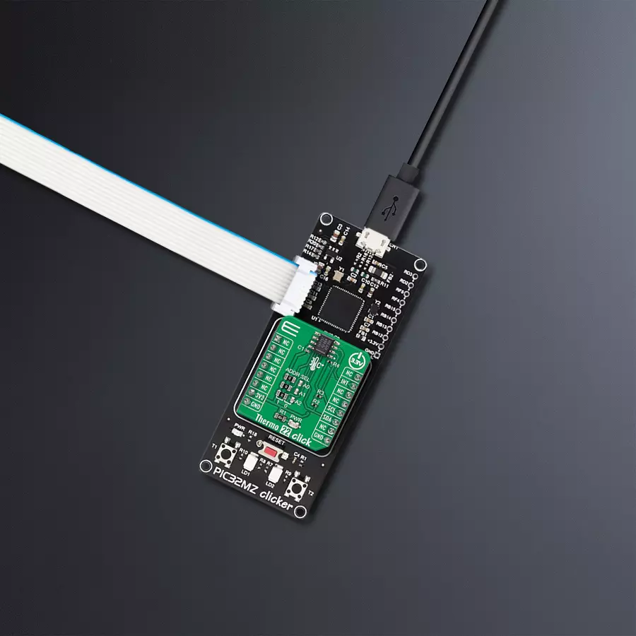
Dev. board
PIC32MZ clicker
Compiler
NECTO Studio
MCU
PIC32MZ1024EFH064
Temperature sensing solution that effortlessly interfaces with your microcontroller, providing accurate temperature data for enhanced system performance
A
A
Hardware Overview
How does it work?
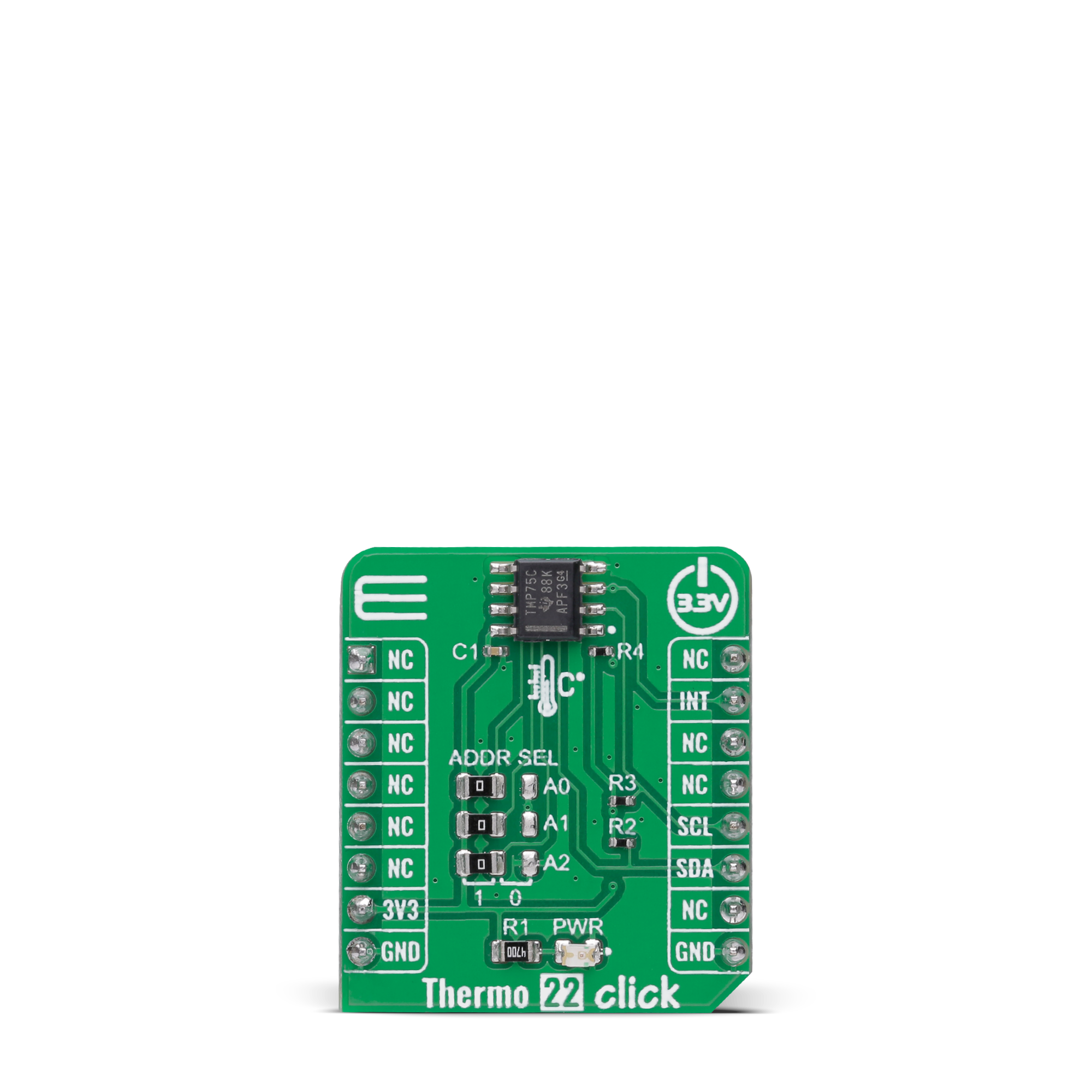
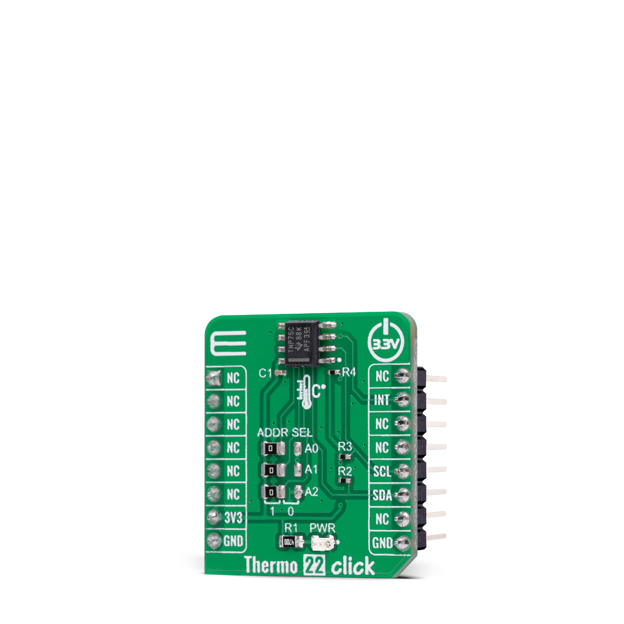
Thermo 22 Click is based on the TMP75C, a digital temperature sensor optimal for thermal management and protection applications from Texas Instruments. This temperature sensor is characterized by high accuracy; a temperature range of 0°C to +70°C provides typical ±0.25°C accuracy. The temperature sensing device for the TMP75C is the chip itself. A bipolar junction transistor inside the chip is used in a band-gap configuration to produce a voltage proportional to the chip temperature. The voltage is digitized and converted to a 12-bit temperature result in degrees Celsius, with a resolution of 0.0625°C. The default operational mode of the TMP75C is Continuous-Conversion mode (CC), where the ADC performs continuous temperature conversions and stores
each result in the temperature register, overwriting the result from the previous conversion. After the Power-Up cycle, the TMP75C immediately starts a conversion. Alongside CC mode, it also has Shutdown and One-shot modes, which reduce power consumption in the TMP75C when continuous temperature monitoring is not required. Thermo 22 Click communicates with MCU using the standard I2C 2-Wire interface to read data and configure settings. Besides, it also allows the choice of the least significant bit of its I2C slave address by positioning the SMD jumpers labeled ADDR SEL to an appropriate position marked as 0 and 1. This way, the TMP75C provides the opportunity of the eight possible different I2C addresses by positioning the SMD jumper to an appropriate position.
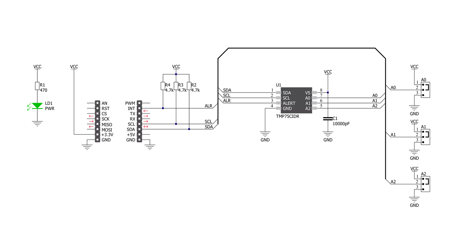
In addition to I2C communication, it uses an interrupt pin routed to the INT pin of the mikroBUS™ socket, representing the programmable temperature limit feature and alert that allows the sensor to operate as a stand-alone thermostat or an overtemperature alarm for system shutdown. This Click board™ can only be operated with a 3.3V logic voltage level. The board must perform appropriate logic voltage level conversion before using MCUs with different logic levels. However, the Click board™ comes equipped with a library containing functions and an example code that can be used as a reference for further development.
Features overview
Development board
PIC32MZ Clicker is a compact starter development board that brings the flexibility of add-on Click boards™ to your favorite microcontroller, making it a perfect starter kit for implementing your ideas. It comes with an onboard 32-bit PIC32MZ microcontroller with FPU from Microchip, a USB connector, LED indicators, buttons, a mikroProg connector, and a header for interfacing with external electronics. Thanks to its compact design with clear and easy-recognizable silkscreen markings, it provides a fluid and immersive working experience, allowing access anywhere and under
any circumstances. Each part of the PIC32MZ Clicker development kit contains the components necessary for the most efficient operation of the same board. In addition to the possibility of choosing the PIC32MZ Clicker programming method, using USB HID mikroBootloader, or through an external mikroProg connector for PIC, dsPIC, or PIC32 programmer, the Clicker board also includes a clean and regulated power supply module for the development kit. The USB Micro-B connection can provide up to 500mA of current, which is more than enough to operate all onboard
and additional modules. All communication methods that mikroBUS™ itself supports are on this board, including the well-established mikroBUS™ socket, reset button, and several buttons and LED indicators. PIC32MZ Clicker is an integral part of the Mikroe ecosystem, allowing you to create a new application in minutes. Natively supported by Mikroe software tools, it covers many aspects of prototyping thanks to a considerable number of different Click boards™ (over a thousand boards), the number of which is growing every day.

Microcontroller Overview
MCU Card / MCU

Architecture
PIC32
MCU Memory (KB)
1024
Silicon Vendor
Microchip
Pin count
64
RAM (Bytes)
524288
Used MCU Pins
mikroBUS™ mapper
Take a closer look
Click board™ Schematic
Step by step
Project assembly

Start by selecting your development board and Click board™. Begin with the PIC32MZ clicker as your development board.


Software Support
Library Description
This library contains API for Thermo 22 Click driver.
Key functions:
thermo22_read_temperatureThis function reads the temperature data in Celsius.thermo22_set_temperature_high_limitThis function sets the temperature high limit at which the overtemperature alert flag is being set.thermo22_get_int_pinThis function returns the INT pin logic state, which indicates the overtemperature alert.
Open Source
Code example
The complete application code and a ready-to-use project are available through the NECTO Studio Package Manager for direct installation in the NECTO Studio. The application code can also be found on the MIKROE GitHub account.
/*!
 * @file main.c
 * @brief Thermo22 Click example
 *
 * # Description
 * This example demonstrates the use of Thermo 22 Click board by reading and displaying
 * the temperature measurements.
 *
 * The demo application is composed of two sections :
 *
 * ## Application Init
 * Initializes the driver and performs the Click default configuration which
 * enables continuous conversation and sets the overtemperature limits to 35.0 Celsius.
 *
 * ## Application Task
 * Reads the temperature measurement in Celsius and displays the results on the USB UART
 * every 200ms approximately. It also checks the overtemperature alert indicator and displays
 * an appropriate message if the indicator is active.
 *
 * @author Stefan Filipovic
 *
 */

#include "board.h"
#include "log.h"
#include "thermo22.h"

static thermo22_t thermo22;
static log_t logger;

void application_init ( void )
{
    log_cfg_t log_cfg;  /**< Logger config object. */
    thermo22_cfg_t thermo22_cfg;  /**< Click config object. */

    /**
     * Logger initialization.
     * Default baud rate: 115200
     * Default log level: LOG_LEVEL_DEBUG
     * @note If USB_UART_RX and USB_UART_TX
     * are defined as HAL_PIN_NC, you will
     * need to define them manually for log to work.
     * See @b LOG_MAP_USB_UART macro definition for detailed explanation.
     */
    LOG_MAP_USB_UART( log_cfg );
    log_init( &logger, &log_cfg );
    log_info( &logger, " Application Init " );

    // Click initialization.
    thermo22_cfg_setup( &thermo22_cfg );
    THERMO22_MAP_MIKROBUS( thermo22_cfg, MIKROBUS_1 );
    if ( I2C_MASTER_ERROR == thermo22_init( &thermo22, &thermo22_cfg ) )
    {
        log_error( &logger, " Communication init." );
        for ( ; ; );
    }

    if ( THERMO22_ERROR == thermo22_default_cfg ( &thermo22 ) )
    {
        log_error( &logger, " Default configuration." );
        for ( ; ; );
    }

    log_info( &logger, " Application Task " );
}

void application_task ( void )
{
    float temperature;
    if ( THERMO22_OK == thermo22_read_temperature ( &thermo22, &temperature ) )
    {
        log_printf ( &logger, " Temperature: %.2f C \r\n\n", temperature );
        if ( !thermo22_get_int_pin ( &thermo22 ) )
        {
            log_printf ( &logger, " Over temperature alert! \r\n\n" );
        }
        Delay_ms ( 200 );
    }
}

int main ( void )
{
    /* Do not remove this line or clock might not be set correctly. */
    #ifdef PREINIT_SUPPORTED
    preinit();
    #endif

    application_init( );

    for ( ; ; )
    {
        application_task( );
    }

    return 0;
}

// ------------------------------------------------------------------------ END
Additional Support
Resources
Category:Temperature & humidity


