Experience the art of signal convergence with TMUX1208 and PIC32MZ2048EFM100
Where signals converge, choices expand!

Published Jul 22, 2025
Click board™
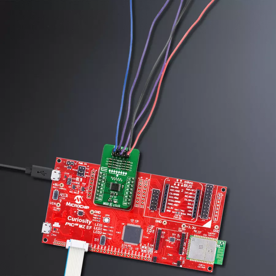
MUX 3 Click
Dev. board
Curiosity PIC32 MZ EF
Compiler
NECTO Studio
MCU
PIC32MZ2048EFM100
Crafted for versatility and precision, our general-purpose CMOS multiplexer empowers you to effortlessly manage and direct various signals, expanding your options for seamless connectivity
A
A
Hardware Overview
How does it work?
MUX 3 Click is based on the TMUX1208, a 5-V Bidirectional 8:1, 1-Channel Multiplexer from Texas Instruments. The TMUX1208 is a general-purpose complementary metal-oxide semiconductor (CMOS) multiplexer (MUX). A wide operating supply of 1.08 V to 5.5 V allows use in various applications, from personal electronics to building automation applications. The device supports bidirectional analog and digital signals on the source (Sx) and drain (D) pins ranging from GND to VDD. All logic inputs have 1.8 V logic-compatible thresholds, ensuring TTL and CMOS logic compatibility when operating in the valid supply voltage range. Fail-Safe Logic circuitry allows voltages on the control pins to be applied before the supply pin, protecting the device from
potential damage. Break-before-make delay is a safety feature that prevents two inputs from connecting when switching devices. The output first breaks from the on-state switch before making the connection with the next on-state switch. The time delay between the break and the make is known as the break-before-make delay. One useful application for the TMUX1208 features is multiplexing various signals into an ADC integrated into an MCU. Utilizing an integrated ADC in the MCU allows a system to minimize cost with a potential tradeoff of system performance when compared to an external ADC. The multiplexer allows for multiple inputs/sensors to be monitored with a single ADC pin of the device, which is critical in systems with limited I/O. Given
all the features the TMUX1208 offers, the MUX 3 Click is best used for Analog and Digital Multiplexing / Demultiplexing, HVAC: Heating, Ventilation, and Air Conditioning, Smoke Detectors, Video Surveillance, Electronic Point of Sale, Battery-Powered Equipment, Appliances, Consumer Audio. This Click board™ can operate with either 3.3V or 5V logic voltage levels selected via the VCC SEL jumper. This way, both 3.3V and 5V capable MCUs can use the communication lines properly. Also, this Click board™ comes equipped with a library containing easy-to-use functions and an example code that can be used, as a reference, for further development.


Features overview
Development board
Curiosity PIC32 MZ EF development board is a fully integrated 32-bit development platform featuring the high-performance PIC32MZ EF Series (PIC32MZ2048EFM) that has a 2MB Flash, 512KB RAM, integrated FPU, Crypto accelerator, and excellent connectivity options. It includes an integrated programmer and debugger, requiring no additional hardware. Users can expand
functionality through MIKROE mikroBUS™ Click™ adapter boards, add Ethernet connectivity with the Microchip PHY daughter board, add WiFi connectivity capability using the Microchip expansions boards, and add audio input and output capability with Microchip audio daughter boards. These boards are fully integrated into PIC32’s powerful software framework, MPLAB Harmony,
which provides a flexible and modular interface to application development a rich set of inter-operable software stacks (TCP-IP, USB), and easy-to-use features. The Curiosity PIC32 MZ EF development board offers expansion capabilities making it an excellent choice for a rapid prototyping board in Connectivity, IOT, and general-purpose applications.

Microcontroller Overview
MCU Card / MCU

Architecture
PIC32
MCU Memory (KB)
2048
Silicon Vendor
Microchip
Pin count
100
RAM (Bytes)
524288
Used MCU Pins
mikroBUS™ mapper
Take a closer look
Click board™ Schematic

Step by step
Project assembly

Start by selecting your development board and Click board™. Begin with the Curiosity PIC32 MZ EF as your development board.


Software Support
Library Description
This library contains API for MUX 3 Click driver.
Key functions:
mux3_set_channel- Set active MUX channel function
Open Source
Code example
The complete application code and a ready-to-use project are available through the NECTO Studio Package Manager for direct installation in the NECTO Studio. The application code can also be found on the MIKROE GitHub account.
/*!
 * \file
 * \brief MUX 3 Click example
 *
 * # Description
 * This application sets multiplexing one input channel to eight single-ended output channels.
 *
 * The demo application is composed of two sections :
 *
 * ## Application Init
 * Initialization driver enable's - GPIO, also write log.
 *
 * ## Application Task
 * This is an example which demonstrates the use of MUX 3 Click board.
 * Sets the current active and changes the channel every 1 sec.
 * Results are being sent to the Usart Terminal where you can track their changes.
 * All data logs write on Usart Terminal changes for every 1 sec.
 *
 * \author MikroE Team
 *
 */
// ------------------------------------------------------------------- INCLUDES

#include "board.h"
#include "log.h"
#include "mux3.h"

// ------------------------------------------------------------------ VARIABLES

static mux3_t mux3;
static log_t logger;

// ------------------------------------------------------ APPLICATION FUNCTIONS

void application_init ( void )
{
    log_cfg_t log_cfg;
    mux3_cfg_t cfg;

    /**
     * Logger initialization.
     * Default baud rate: 115200
     * Default log level: LOG_LEVEL_DEBUG
     * @note If USB_UART_RX and USB_UART_TX
     * are defined as HAL_PIN_NC, you will
     * need to define them manually for log to work.
     * See @b LOG_MAP_USB_UART macro definition for detailed explanation.
     */
    LOG_MAP_USB_UART( log_cfg );
    log_init( &logger, &log_cfg );
    log_info(&logger, "---- Application Init ----");

    //  Click initialization.

    mux3_cfg_setup( &cfg );
    MUX3_MAP_MIKROBUS( cfg, MIKROBUS_1 );
    mux3_init( &mux3, &cfg );
}

void application_task ( void )
{
    mux3_set_channel( &mux3, MUX3_ENABLE_CHANNEL_S1 );
    log_printf( &logger, "Active channel: S1\r\n" );
    Delay_1sec( );

    mux3_set_channel( &mux3, MUX3_ENABLE_CHANNEL_S2 );
    log_printf( &logger, "Active channel: S2\r\n" );
    Delay_1sec( );

    mux3_set_channel( &mux3, MUX3_ENABLE_CHANNEL_S3 );
    log_printf( &logger, "Active channel: S3\r\n" );
    Delay_1sec( );

    mux3_set_channel( &mux3, MUX3_ENABLE_CHANNEL_S4 );
    log_printf( &logger, "Active channel: S4\r\n" );
    Delay_1sec( );

    mux3_set_channel( &mux3, MUX3_ENABLE_CHANNEL_S5 );
    log_printf( &logger, "Active channel: S5\r\n" );
    Delay_1sec( );

    mux3_set_channel( &mux3, MUX3_ENABLE_CHANNEL_S6 );
    log_printf( &logger, "Active channel: S6\r\n" );
    Delay_1sec( );

    mux3_set_channel( &mux3, MUX3_ENABLE_CHANNEL_S7 );
    log_printf( &logger, "Active channel: S7\r\n" );
    Delay_1sec( );

    mux3_set_channel( &mux3, MUX3_ENABLE_CHANNEL_S8 );
    log_printf( &logger, "Active channel: S8\r\n" );
    Delay_1sec( );

    mux3_set_channel( &mux3, MUX3_DISABLE_ALL_CHANNELS );
    log_printf( &logger, "Active channel: none\r\n" );
    log_printf( &logger, "-------------------\r\n" );
    Delay_1sec( );
}

int main ( void )
{
    /* Do not remove this line or clock might not be set correctly. */
    #ifdef PREINIT_SUPPORTED
    preinit();
    #endif

    application_init( );

    for ( ; ; )
    {
        application_task( );
    }

    return 0;
}

// ------------------------------------------------------------------------ END
Additional Support
Resources
Category:DAC


