Get insights into muscle activity with MCP609 and ATmega644
Optimize your workouts with monitoring

Published Jul 27, 2023
Click board™
EMG Click
Dev. board
EasyAVR v7
Compiler
NECTO Studio
MCU
ATmega644
Enhance your solution's diagnostic capabilities by incorporating cutting-edge techniques for measuring the electrical activity of muscles, providing precise and valuable insights into muscular performance and health
A
A
Hardware Overview
How does it work?
EMG Click is based on the MCP609 operational amplifier from Microchip and MAX6106 micropower voltage reference, serving as a solution that measures the electrical activity produced by the skeletal muscles. EMG click is designed to run on a 5V power supply. The click board™ has an analog output (AN pin).
Electromyography, or EMG, is a diagnostic technique for measuring the electrical activity of muscles. It is often used to diagnose the health of these muscles and the neurons that control them. These neurons are called motor neurons. They transmit electrical signals, and the muscles contract when this happens.
An EMG collects these signals and translates them into a graphical representation. The onboard 3.5mm audio jack is used to connect cables/electrodes to the click board. The electrode collects voltage from the skin (a few millivolts). And the signal from the jack is amplified and filtered. Therefore, EMG Click can be divided into seven blocks.

Features overview
Development board
EasyAVR v7 is the seventh generation of AVR development boards specially designed for the needs of rapid development of embedded applications. It supports a wide range of 16-bit AVR microcontrollers from Microchip and has a broad set of unique functions, such as a powerful onboard mikroProg programmer and In-Circuit debugger over USB. The development board is well organized and designed so that the end-user has all the necessary elements in one place, such as switches, buttons, indicators, connectors, and others. With four different connectors for each port, EasyAVR v7 allows you to connect accessory boards, sensors, and custom electronics more
efficiently than ever. Each part of the EasyAVR v7 development board contains the components necessary for the most efficient operation of the same board. An integrated mikroProg, a fast USB 2.0 programmer with mikroICD hardware In-Circuit Debugger, offers many valuable programming/debugging options and seamless integration with the Mikroe software environment. Besides it also includes a clean and regulated power supply block for the development board. It can use a wide range of external power sources, including an external 12V power supply, 7-12V AC or 9-15V DC via DC connector/screw terminals, and a power source via the USB Type-B (USB-B)
connector. Communication options such as USB-UART and RS-232 are also included, alongside the well-established mikroBUS™ standard, three display options (7-segment, graphical, and character-based LCD), and several different DIP sockets which cover a wide range of 16-bit AVR MCUs. EasyAVR v7 is an integral part of the Mikroe ecosystem for rapid development. Natively supported by Mikroe software tools, it covers many aspects of prototyping and development thanks to a considerable number of different Click boards™ (over a thousand boards), the number of which is growing every day.

Microcontroller Overview
MCU Card / MCU

Architecture
AVR
MCU Memory (KB)
64
Silicon Vendor
Microchip
Pin count
40
RAM (Bytes)
4096
You complete me!
Accessories
3-wire ECG/EMG cable comes with a convenient 3.5mm phone jack, and it is designed for electrocardiogram recording. This 1m cable is a practical companion for medical professionals and enthusiasts. To complement this cable, you can also use single-use adhesive ECG/EMG electrodes measuring 48x34mm, each equipped with an ECG/EMG cable stud adapter. These electrodes ensure a seamless experience when paired with our ECG/EMG cable and guarantee reliable ECG/EMG signal transmission for comprehensive cardiac monitoring. Trust in the accuracy and convenience of this setup to effortlessly record electrocardiograms and electromyograms with confidence.

Used MCU Pins
mikroBUS™ mapper
Take a closer look
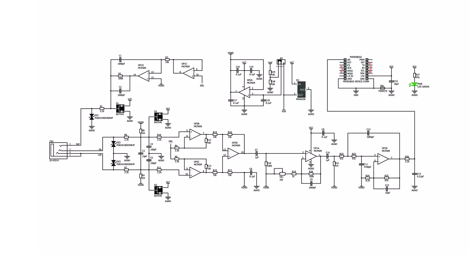
Click board™ Schematic
Step by step
Project assembly

Start by selecting your development board and Click board™. Begin with the EasyAVR v7 as your development board.


Software Support
Library Description
This library contains API for EMG Click driver.
Key functions:
emg_read_an_pin_value- EMG read AN pin value functionemg_read_an_pin_voltage- EMG read AN pin voltage level function
Open Source
Code example
The complete application code and a ready-to-use project are available through the NECTO Studio Package Manager for direct installation in the NECTO Studio. The application code can also be found on the MIKROE GitHub account.
/*!
 * @file main.c
 * @brief EMG Click Example.
 *
 * # Description
 * This is an example which demonstrates the use of EMG Click board.
 *
 * The demo application is composed of two sections :
 *
 * ## Application Init
 * Initializes ADC and timer counter.
 *
 * ## Application Task
 * Reads ADC value and sends results on serial plotter every 5 ms.
 *
 * @author Stefan Ilic
 *
 */

#include "board.h"
#include "log.h"
#include "emg.h"

static emg_t emg;   /**< EMG Click driver object. */
static log_t logger;    /**< Logger object. */
uint32_t time;

void application_init ( void ) {
    log_cfg_t log_cfg;  /**< Logger config object. */
    emg_cfg_t emg_cfg;  /**< Click config object. */

    /**
     * Logger initialization.
     * Default baud rate: 115200
     * Default log level: LOG_LEVEL_DEBUG
     * @note If USB_UART_RX and USB_UART_TX
     * are defined as HAL_PIN_NC, you will
     * need to define them manually for log to work.
     * See @b LOG_MAP_USB_UART macro definition for detailed explanation.
     */
    LOG_MAP_USB_UART( log_cfg );
    log_init( &logger, &log_cfg );
    log_info( &logger, " Application Init " );

    // Click initialization.
    emg_cfg_setup( &emg_cfg );
    EMG_MAP_MIKROBUS( emg_cfg, MIKROBUS_1 );
    if ( ADC_ERROR == emg_init( &emg, &emg_cfg ) ) {
        log_error( &logger, " Application Init Error. " );
        log_info( &logger, " Please, run program again... " );

        for ( ; ; );
    }
    time = 0;
    log_info( &logger, " Application Task " );
}

void application_task ( void )  {
    uint16_t emg_an = 0;
    if ( emg_read_an_pin_value( &emg, &emg_an ) == ADC_SUCCESS ){
        log_printf( &logger, " %u,%lu\r\n ", emg_an, time );
    }
    time += 5;
    Delay_ms ( 5 );
}

int main ( void )
{
    /* Do not remove this line or clock might not be set correctly. */
    #ifdef PREINIT_SUPPORTED
    preinit();
    #endif

    application_init( );

    for ( ; ; )
    {
        application_task( );
    }

    return 0;
}

// ------------------------------------------------------------------------ END


