Customize motion experience with MMA8491Q and PIC32MZ1024EFH064
Accurate motion insights at your fingertips

Published Jun 22, 2023
Click board™
TILTnSHAKE Click
Dev. board
PIC32MZ clicker
Compiler
NECTO Studio
MCU
PIC32MZ1024EFH064
Transform your solution with a cutting-edge three-axis digital accelerometer, unlock precise motion sensing, and elevate performance
A
A
Hardware Overview
How does it work?
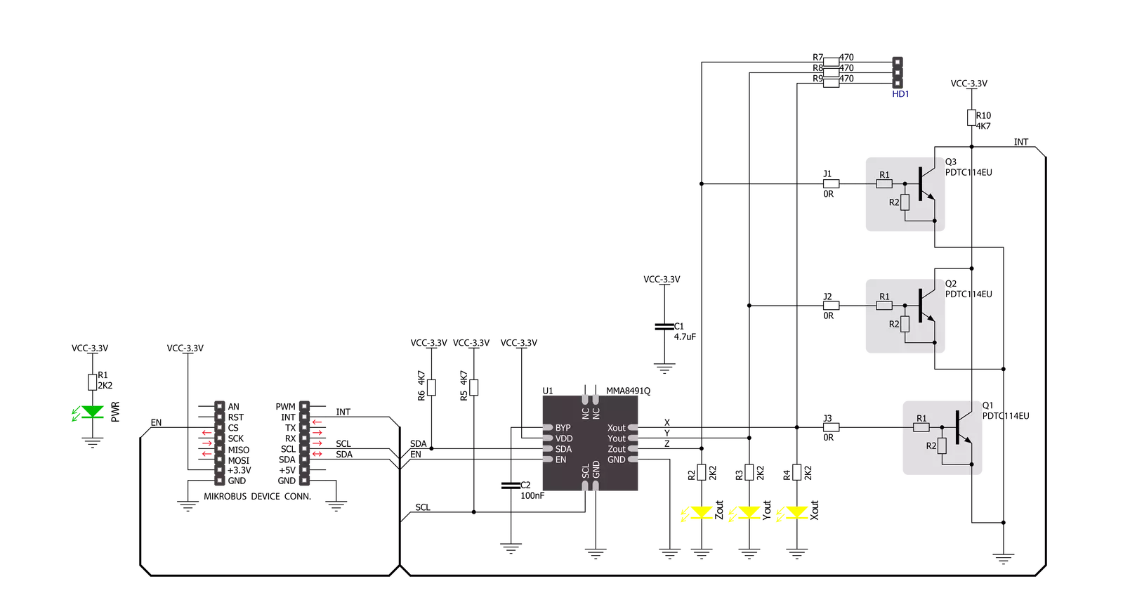
Tilt-n-Shake Click is based on the MMA8491Q, a multifunctional 3-axis digital accelerometer from NXP Semiconductors that enables the lowest power consumption for low data rate accelerometer applications. It can accommodate two accelerometer configurations, acting as a digital output accelerometer or a 45° tilt sensor with the addition of a visual indication of the tilt axis. The MMA8491Q is flexible and useful for various applications beyond smart metering in which orientation must be accurately measured and for tracking assets in business and industrial applications. This Click board™ communicates with MCU using the standard I2C 2-Wire interface to read data and configure settings, supporting Fast Mode up to 400kHz. The MMA8491Q can be
enabled or disabled through the EN pin routed to the CS pin of the mikroBUS™ socket, hence, offering a switch operation to turn ON/OFF the accelerometer system. Also, the MMA8491Q must be in an Active state of operation when the data is being polled (EN pin must be set in the high logic state). The 14-bit ±8g accelerometer data can be read via the I2C 2-Wire interface with a 1 mg/LSB sensitivity. On the other hand, as a 45° tilt sensor, the MMA8491Q offers a single line output per axis through the X, Y, and Z pins. These pins are asserted whenever the tilt angle in the respective axis is greater than 45°. The information from these pins can be processed through the INT pin of the mikroBUS™ socket, allowing the user to select which tilt axes to detect, or it is also possible
to use them externally in the configuration that best suits the user through an additional unpopulated tilt header. The population makes tilt axis information selection of corresponding X, Y, and Z jumpers marked with INT SEL. It is also possible to visually identify each of these axes through onboard yellow LEDs. This Click board™ can be operated only with a 3.3V logic voltage level. The board must perform appropriate logic voltage level conversion before using MCUs with different logic levels. However, the Click board™ comes equipped with a library containing functions and an example code that can be used as a reference for further development.

Features overview
Development board
PIC32MZ Clicker is a compact starter development board that brings the flexibility of add-on Click boards™ to your favorite microcontroller, making it a perfect starter kit for implementing your ideas. It comes with an onboard 32-bit PIC32MZ microcontroller with FPU from Microchip, a USB connector, LED indicators, buttons, a mikroProg connector, and a header for interfacing with external electronics. Thanks to its compact design with clear and easy-recognizable silkscreen markings, it provides a fluid and immersive working experience, allowing access anywhere and under
any circumstances. Each part of the PIC32MZ Clicker development kit contains the components necessary for the most efficient operation of the same board. In addition to the possibility of choosing the PIC32MZ Clicker programming method, using USB HID mikroBootloader, or through an external mikroProg connector for PIC, dsPIC, or PIC32 programmer, the Clicker board also includes a clean and regulated power supply module for the development kit. The USB Micro-B connection can provide up to 500mA of current, which is more than enough to operate all onboard
and additional modules. All communication methods that mikroBUS™ itself supports are on this board, including the well-established mikroBUS™ socket, reset button, and several buttons and LED indicators. PIC32MZ Clicker is an integral part of the Mikroe ecosystem, allowing you to create a new application in minutes. Natively supported by Mikroe software tools, it covers many aspects of prototyping thanks to a considerable number of different Click boards™ (over a thousand boards), the number of which is growing every day.

Microcontroller Overview
MCU Card / MCU

Architecture
PIC32
MCU Memory (KB)
1024
Silicon Vendor
Microchip
Pin count
64
RAM (Bytes)
524288
Used MCU Pins
mikroBUS™ mapper
Take a closer look
Click board™ Schematic
Step by step
Project assembly

Start by selecting your development board and Click board™. Begin with the PIC32MZ clicker as your development board.


Software Support
Library Description
This library contains API for Tilt-n-Shake Click driver.
Key functions:
tiltnshake_read_status_and_axis- Function for read status and axistiltnshake_conversion- Function for conversiontiltnshake_enable- Function for enabled chip
Open Source
Code example
The complete application code and a ready-to-use project are available through the NECTO Studio Package Manager for direct installation in the NECTO Studio. The application code can also be found on the MIKROE GitHub account.
/*!
 * \file
 * \brief TiltNshake Click example
 *
 * # Description
 * This application is multifunctional 3-axis digital accelerometer
 * that can also be configured as a 45-degree Tilt sensor.
 *
 * The demo application is composed of two sections :
 *
 * ## Application Init
 * Initializes device.
 *
 * ## Application Task
 * Reads 3-axis accelerometer measurement and logs results on the USB UART.
 *
 * \author MikroE Team
 *
 */

#include "board.h"
#include "log.h"
#include "tiltnshake.h"

static tiltnshake_t tiltnshake;
static log_t logger;

void application_init ( void )
{
    log_cfg_t log_cfg;
    tiltnshake_cfg_t cfg;

    /**
     * Logger initialization.
     * Default baud rate: 115200
     * Default log level: LOG_LEVEL_DEBUG
     * @note If USB_UART_RX and USB_UART_TX
     * are defined as HAL_PIN_NC, you will
     * need to define them manually for log to work.
     * See @b LOG_MAP_USB_UART macro definition for detailed explanation.
     */
    LOG_MAP_USB_UART( log_cfg );
    log_init( &logger, &log_cfg );
    log_info( &logger, " Application Init " );

    // Click initialization.
    tiltnshake_cfg_setup( &cfg );
    TILTNSHAKE_MAP_MIKROBUS( cfg, MIKROBUS_1 );
    tiltnshake_init( &tiltnshake, &cfg );

    log_info( &logger, " Application Task " );
}

void application_task ( void )
{
    uint8_t status = 0;
    float out_x = 0;
    float out_y = 0;
    float out_z = 0;

    tiltnshake_enable( &tiltnshake );
    tiltnshake_read_status_and_axis( &tiltnshake, &status, &out_x, &out_y, &out_z );
    tiltnshake_disable( &tiltnshake );

    if ( TILTNSHAKE_DATA_READY == status )
    {
        log_printf( &logger, " X: %.2f\r\n", out_x );
        log_printf( &logger, " Y: %.2f\r\n", out_y );
        log_printf( &logger, " Z: %.2f\r\n", out_z );
        log_printf( &logger, "----------\r\n");
        Delay_ms ( 500 );
    }
    Delay_ms ( 500 );
}

int main ( void )
{
    /* Do not remove this line or clock might not be set correctly. */
    #ifdef PREINIT_SUPPORTED
    preinit();
    #endif

    application_init( );

    for ( ; ; )
    {
        application_task( );
    }

    return 0;
}

// ------------------------------------------------------------------------ END
Additional Support
Resources
Category:Motion


