Improve user experiences and simplify interactions with ADXL362 and MK64FN1M0VDC12
Tap to transform: The magic of movement-activated solutions
Published Oct 05, 2023
Click board™
Shake2Wake Click
Dev. board
Clicker 2 for Kinetis
Compiler
NECTO Studio
MCU
MK64FN1M0VDC12
This solution opens the door to a new era of automation and accessibility, enabling devices and systems to respond seamlessly to human movement
A
A
Hardware Overview
How does it work?
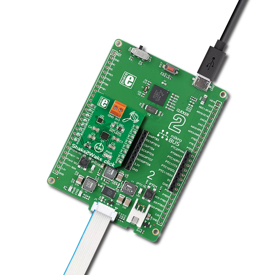
Shake2Wake Click is based on the ADXL362, a digital output 3-axis MEMS accelerometer, and the ADP195, a logic-controlled high-side power switch with reverse current blocking, both from Analog Devices. The ultralow-power ADXL362 features an on-chip temperature sensor, a high resolution of 1mg/LSB detection with ranges of ±2 g, ±4 g, and ±8, low noise, and acceleration sample synchronization via an external trigger. The ADXL362 comes with various features for system-level power savings, such as adjustable thresholds for motion activation, autonomous interrupt processing without the need for the host MCU intervention that allows the rest of the system to be turned off completely, deep embedded
FIFO, and more. The ADXL362 also provides a 12-bit output resolution and 8-bit data for more efficient single-byte transfers when a lower resolution is sufficient. This Click board™ has two main operating modes: measuring and wake-up. For use as a regular accelerometer, for continuous sensing, use the measurement mode. The ADP195 on this Click board™ is an onboard power switch that controls an external device connected through a screw terminal. The load switch isolates the power domain and protects against the reverse current flow from output to input. The ADXL362 uses an SPI serial interface to communicate with the host microcontroller. Several of the built-in functions of the ADXL362
can trigger interrupts to alert the host MCU of certain status conditions. The ADXL362 can use INT1 or INT2 selected over the INT SEL jumper to meet the mapped condition expected to be activated, with INT2 chosen by default. The ADXL362's interrupt is also connected to the host MCU over the INT pin, enabling the ADP195 when movement occurs. This Click board™ can be operated only with a 3.3V logic voltage level. The board must perform appropriate logic voltage level conversion before using MCUs with different logic levels. Also, it comes equipped with a library containing functions and an example code that can be used as a reference for further development.

Features overview
Development board
Clicker 2 for Kinetis is a compact starter development board that brings the flexibility of add-on Click boards™ to your favorite microcontroller, making it a perfect starter kit for implementing your ideas. It comes with an onboard 32-bit ARM Cortex-M4F microcontroller, the MK64FN1M0VDC12 from NXP Semiconductors, two mikroBUS™ sockets for Click board™ connectivity, a USB connector, LED indicators, buttons, a JTAG programmer connector, and two 26-pin headers for interfacing with external electronics. Its compact design with clear and easily recognizable silkscreen markings allows you to build gadgets with unique functionalities and
features quickly. Each part of the Clicker 2 for Kinetis development kit contains the components necessary for the most efficient operation of the same board. In addition to the possibility of choosing the Clicker 2 for Kinetis programming method, using a USB HID mikroBootloader or an external mikroProg connector for Kinetis programmer, the Clicker 2 board also includes a clean and regulated power supply module for the development kit. It provides two ways of board-powering; through the USB Micro-B cable, where onboard voltage regulators provide the appropriate voltage levels to each component on the board, or
using a Li-Polymer battery via an onboard battery connector. All communication methods that mikroBUS™ itself supports are on this board, including the well-established mikroBUS™ socket, reset button, and several user-configurable buttons and LED indicators. Clicker 2 for Kinetis is an integral part of the Mikroe ecosystem, allowing you to create a new application in minutes. Natively supported by Mikroe software tools, it covers many aspects of prototyping thanks to a considerable number of different Click boards™ (over a thousand boards), the number of which is growing every day.

Microcontroller Overview
MCU Card / MCU

Architecture
ARM Cortex-M4
MCU Memory (KB)
1024
Silicon Vendor
NXP
Pin count
121
RAM (Bytes)
262144
Used MCU Pins
mikroBUS™ mapper
Take a closer look
Click board™ Schematic
Step by step
Project assembly

Start by selecting your development board and Click board™. Begin with the Clicker 2 for Kinetis as your development board.


Software Support
Library Description
This library contains API for Shake2Wake Click driver.
Key functions:
shake2wake_get_lo_res_raw_data- This function is used to read 8-bit acceleration data per axisshake2wake_get_raw_data- This function is used to read the 3-axis raw data from the accelerometershake2wake_read_temperature- This function is used to read temperature from an internal sensor
Open Source
Code example
The complete application code and a ready-to-use project are available through the NECTO Studio Package Manager for direct installation in the NECTO Studio. The application code can also be found on the MIKROE GitHub account.
/*!
 * \file
 * \brief Shake2Wake Click example
 *
 * # Description
 * This app shows the capabilities of the Shake2Wake Click by
 * reading values of an accelerometer.
 *
 * The demo application is composed of two sections :
 *
 * ## Application Init
 * Initalizes device and applies default settings.
 *
 * ## Application Task
 * This is an example that shows the capabilities of the Shake2Wake Click by
 * reading values of an accelerometer and logging them on USART terminal and,
 * in case of an interrupt, it raises voltage on the connector.
 *
 * \author MikroE Team
 *
 */
// ------------------------------------------------------------------- INCLUDES

#include "board.h"
#include "log.h"
#include "shake2wake.h"

// ------------------------------------------------------------------ VARIABLES

static shake2wake_t shake2wake;
static log_t logger;

// ------------------------------------------------------ APPLICATION FUNCTIONS

void application_init ( void )
{
    log_cfg_t log_cfg;
    shake2wake_cfg_t cfg;

    /**
     * Logger initialization.
     * Default baud rate: 115200
     * Default log level: LOG_LEVEL_DEBUG
     * @note If USB_UART_RX and USB_UART_TX
     * are defined as HAL_PIN_NC, you will
     * need to define them manually for log to work.
     * See @b LOG_MAP_USB_UART macro definition for detailed explanation.
     */
    LOG_MAP_USB_UART( log_cfg );
    log_init( &logger, &log_cfg );
    log_info( &logger, "---- Application Init ----" );

    //  Click initialization.
    shake2wake_cfg_setup( &cfg );
    SHAKE2WAKE_MAP_MIKROBUS( cfg, MIKROBUS_1 );
    shake2wake_init( &shake2wake, &cfg );
    Delay_ms ( 100 );

    log_printf( &logger, "--------------------------\r\n" );
    log_printf( &logger, "    Shake2Wake  Click     \r\n" );
    log_printf( &logger, "--------------------------\r\n" );

    shake2wake_default_cfg( &shake2wake );
    Delay_ms ( 1000 );
}

void application_task ( void )
{
    float temperature = 0;
    int16_t x_val = 0;
    int16_t y_val = 0;
    int16_t z_val = 0;

    shake2wake_get_raw_data( &shake2wake, &x_val, &y_val, &z_val );
    temperature = shake2wake_read_temperature( &shake2wake );

    log_printf( &logger, "X axis: %d\r\n", x_val );
    log_printf( &logger, "Y axis: %d\r\n", y_val );
    log_printf( &logger, "Z axis: %d\r\n", z_val );
    log_printf( &logger, "Temperature: %.2f degC\r\n", temperature );
    log_printf( &logger, "--------------------------\r\n" );
    Delay_ms ( 1000 );
}

int main ( void )
{
    /* Do not remove this line or clock might not be set correctly. */
    #ifdef PREINIT_SUPPORTED
    preinit();
    #endif

    application_init( );

    for ( ; ; )
    {
        application_task( );
    }

    return 0;
}

// ------------------------------------------------------------------------ END
Additional Support
Resources
Category:Motion


