Create some serious wireless wonders with CYBT-343026-01 and MK64FN1M0VDC12
Simplify your life with Bluetooth

Published Jul 29, 2023
Click board™
BT-EZ Click
Dev. board
Clicker 2 for Kinetis
Compiler
NECTO Studio
MCU
MK64FN1M0VDC12
Stream, share, and control data between compatible devices with unmatched ease
A
A
Hardware Overview
How does it work?
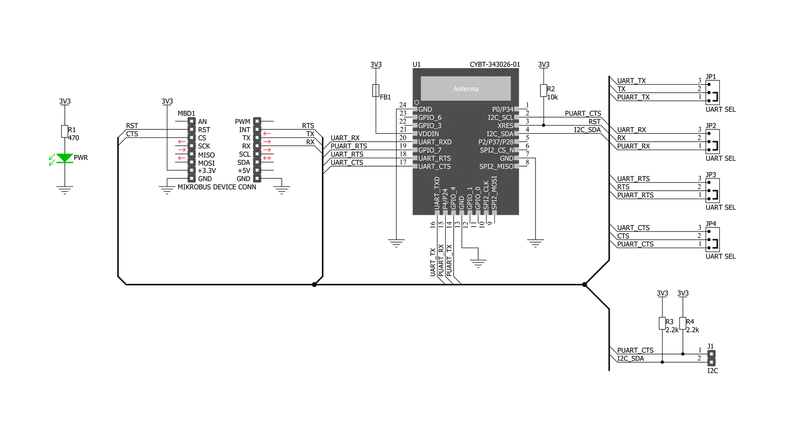
BT-EZ Click is based on the CYBT-343026-01, a module from Infineon that has some impressive features, including the fact that it includes a royalty-free Bluetooth stack with Bluetooth 5.0 and BLE supported. Besides that, low power mode enables the module to consume as low as 2.69µA in deep sleep mode, which is ideal for portable, wearable, and various other battery-powered devices and applications. The BT-EZ Click is a fully integrated Bluetooth smart-ready wireless module with an onboard crystal oscillator, passive components, flash memory, and the CYW20706 silicon device from Infineon. The CYBT-343026-01 module also includes a Cortex-M3 32-bit processor and 512 KB of onboard serial flash memory. It is designed for standalone operation, while the integrated power amplifier is used to achieve Class I or II output power capability. The BT-EZ click board uses UART communication and GPIO pins
for communication with the main MCU. The BT-EZ Click supports two UART communication modes. HCI UART intercafe is a standard, 4-wire interface (RX, TX, RTS, and CTS) with adjustable baud rates from 38400 bps to 4 Mbps. During initial boot, UART speeds may be limited to 750 kbps. The baud rate may be selected via a vendor-specific UART HCI command. The UART clock default setting is 24MHz and can run as high as 48 MHz to support up to 4 Mbps. The baud rate of the CYBT-343026-01UART module is controlled by two values: the clock divisor (set in the DLBR register) that divides the UART clock by an integer multiple of 16, and the baud rate adjustment (set in the DHBR register) that is used to specify the number of UART clock cycles to stuff in the first or second half of each bit time. The BT-EZ click has a second UART (PUART) mode that may be used to interface with other peripherals. This peripheral UART is
accessed through the optional I/O ports, which can be configured individually and separately for each signal. The external I2C pad provides a 2-pin master I2C interface, which can retrieve configuration information from an external EEPROM or communicate with peripherals such as track-ball or touch-pad modules and motion-tracking ICs used in mouse devices. This interface is compatible with I2C slave devices. I2C does not support multi-master capability or flexible wait-state insertion by either master or slave devices. This Click board™ can be operated only with a 3.3V logic voltage level. The board must perform appropriate logic voltage level conversion before using MCUs with different logic levels. Also, it comes equipped with a library containing functions and an example code that can be used, as a reference, for further development.


Features overview
Development board
Clicker 2 for Kinetis is a compact starter development board that brings the flexibility of add-on Click boards™ to your favorite microcontroller, making it a perfect starter kit for implementing your ideas. It comes with an onboard 32-bit ARM Cortex-M4F microcontroller, the MK64FN1M0VDC12 from NXP Semiconductors, two mikroBUS™ sockets for Click board™ connectivity, a USB connector, LED indicators, buttons, a JTAG programmer connector, and two 26-pin headers for interfacing with external electronics. Its compact design with clear and easily recognizable silkscreen markings allows you to build gadgets with unique functionalities and
features quickly. Each part of the Clicker 2 for Kinetis development kit contains the components necessary for the most efficient operation of the same board. In addition to the possibility of choosing the Clicker 2 for Kinetis programming method, using a USB HID mikroBootloader or an external mikroProg connector for Kinetis programmer, the Clicker 2 board also includes a clean and regulated power supply module for the development kit. It provides two ways of board-powering; through the USB Micro-B cable, where onboard voltage regulators provide the appropriate voltage levels to each component on the board, or
using a Li-Polymer battery via an onboard battery connector. All communication methods that mikroBUS™ itself supports are on this board, including the well-established mikroBUS™ socket, reset button, and several user-configurable buttons and LED indicators. Clicker 2 for Kinetis is an integral part of the Mikroe ecosystem, allowing you to create a new application in minutes. Natively supported by Mikroe software tools, it covers many aspects of prototyping thanks to a considerable number of different Click boards™ (over a thousand boards), the number of which is growing every day.

Microcontroller Overview
MCU Card / MCU

Architecture
ARM Cortex-M4
MCU Memory (KB)
1024
Silicon Vendor
NXP
Pin count
121
RAM (Bytes)
262144
Used MCU Pins
mikroBUS™ mapper
Take a closer look
Click board™ Schematic
Step by step
Project assembly

Start by selecting your development board and Click board™. Begin with the Clicker 2 for Kinetis as your development board.


Software Support
Library Description
This library contains API for BT-EZ Click driver.
Key functions:
btez_generic_write- Generic write functionbtez_generic_read- Generic read functionbtez_send_command- Send command function
Open Source
Code example
The complete application code and a ready-to-use project are available through the NECTO Studio Package Manager for direct installation in the NECTO Studio. The application code can also be found on the MIKROE GitHub account.
/*!
 * \file
 * \brief BtEz Click example
 *
 * # Description
 * This example reads and processes data from BT-EZ Clicks.
 *
 * The demo application is composed of two sections :
 *
 * ## Application Init
 * Initializes the driver and configures the Click board.
 *
 * ## Application Task
 * Checks for the received data, reads it and replies with a certain message.
 *
 * ## Additional Function
 * - btez_process ( ) - Logs all received messages on UART, and sends the certain
 * message back to the connected device.
 *
 * @note
 * We have used the Serial Bluetooth Terminal smartphone application for the test.
 * A smartphone and the Click board must be paired in order to exchange messages
 * with each other.
 *
 * \author MikroE Team
 *
 */
// ------------------------------------------------------------------- INCLUDES

#include "board.h"
#include "log.h"
#include "btez.h"
#include "string.h"

#define PROCESS_COUNTER 100
#define PROCESS_RX_BUFFER_SIZE 200

#define CMD_PING           "/PING"
#define CMD_DEVICE_NAME    "SDN,N=BT-EZ_Click"
#define CMD_SAVE           "SDA$,A=0080"
#define CMD_GDN            "GDN"
#define SEND_DATA          "MikroE // BT-EZ Click\r\n"

// ------------------------------------------------------------------ VARIABLES

static btez_t btez;
static log_t logger;
static uint8_t config_mode = 0;
static char current_parser_buf[ PROCESS_RX_BUFFER_SIZE ];

// ------------------------------------------------------- ADDITIONAL FUNCTIONS

static void btez_process ( void )
{
    int32_t rsp_size;
    uint16_t rsp_cnt = 0;
    uint8_t ret_flag = 0;

    char uart_rx_buffer[ PROCESS_RX_BUFFER_SIZE ] = { 0 };
    uint8_t check_buf_cnt;
    uint8_t process_cnt = PROCESS_COUNTER;

    // Clear current buffer
    memset( current_parser_buf, 0, PROCESS_RX_BUFFER_SIZE );

    while( process_cnt != 0 )
    {
        rsp_size = btez_generic_read( &btez, &uart_rx_buffer, PROCESS_RX_BUFFER_SIZE );

        if ( rsp_size > 0 )
        {
            // Validation of the received data
            for ( check_buf_cnt = 0; check_buf_cnt < rsp_size; check_buf_cnt++ )
            {
                if ( uart_rx_buffer[ check_buf_cnt ] == 0 )
                {
                    uart_rx_buffer[ check_buf_cnt ] = 13;
                }
            }
            // Storages data in current buffer
            rsp_cnt += rsp_size;
            if ( rsp_cnt < PROCESS_RX_BUFFER_SIZE )
            {
                strncat( current_parser_buf, uart_rx_buffer, rsp_size );
            }

            if ( strchr ( uart_rx_buffer, '@' ) )
            {
                ret_flag = 1;
                process_cnt = 3;
            }
            else if ( config_mode == 0 )
            {
                btez_send_command( &btez, SEND_DATA );
                ret_flag = 2;
                process_cnt = 3;
            }

            // Clear RX buffer
            memset( uart_rx_buffer, 0, PROCESS_RX_BUFFER_SIZE );
        }
        else
        {
            process_cnt--;

            // Process delay
            Delay_ms ( 100 );
        }
    }

    if ( ret_flag != 0 )
    {
        log_printf( &logger, "%s", current_parser_buf );
    }
}

// ------------------------------------------------------ APPLICATION FUNCTIONS

void application_init ( void )
{
    log_cfg_t log_cfg;
    btez_cfg_t cfg;

    /**
     * Logger initialization.
     * Default baud rate: 115200
     * Default log level: LOG_LEVEL_DEBUG
     * @note If USB_UART_RX and USB_UART_TX
     * are defined as HAL_PIN_NC, you will
     * need to define them manually for log to work.
     * See @b LOG_MAP_USB_UART macro definition for detailed explanation.
     */
    LOG_MAP_USB_UART( log_cfg );
    log_init( &logger, &log_cfg );
    log_info( &logger, "---- Application Init ----" );

    //  Click initialization.

    btez_cfg_setup( &cfg );
    BTEZ_MAP_MIKROBUS( cfg, MIKROBUS_1 );
    btez_init( &btez, &cfg );
    Delay_ms ( 100 );

    log_printf( &logger, "Configuring the module...\r\n" );
    config_mode = 1;

    btez_module_reset( &btez );
    btez_process( );
    btez_send_command( &btez, CMD_PING );
    btez_process( );
    btez_send_command( &btez, CMD_DEVICE_NAME );
    btez_process( );
    btez_send_command( &btez, CMD_SAVE );
    btez_process( );
    btez_send_command( &btez, CMD_GDN );
    btez_process( );

    config_mode = 0;
    log_printf( &logger, "The module has been configured.\r\n" );
    Delay_1sec( );
}

void application_task ( void )
{
    btez_process( );
}

int main ( void )
{
    /* Do not remove this line or clock might not be set correctly. */
    #ifdef PREINIT_SUPPORTED
    preinit();
    #endif

    application_init( );

    for ( ; ; )
    {
        application_task( );
    }

    return 0;
}

// ------------------------------------------------------------------------ END


