Take your audio to new heights with LM4860 and MK64FN1M0VDC12
Amplify every beat, enhance every note!

Published Jun 02, 2023
Click board™
AudioAmp 4 Click
Dev. board
Clicker 2 for Kinetis
Compiler
NECTO Studio
MCU
MK64FN1M0VDC12
Enhance your embedded solution's audio performance and invest in the future of audio technology with our advanced audio amplifier
A
A
Hardware Overview
How does it work?
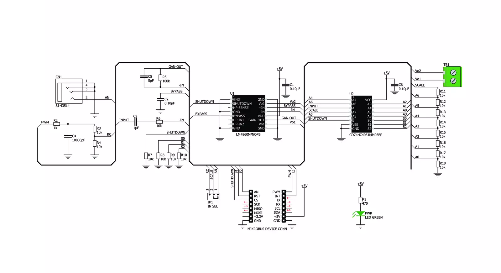
AudioAmp 4 Click is based on the LM4860, a Boomer® series 1W audio power amplifier with shutdown mode from Texas Instruments. Besides the LM4860, there is also the CD74HC4051, a high-speed CMOS logic analog mux/demux IC from Texas Instruments. The LM4860 is used as the main audio amplifier component. This IC features a high level of integration, reducing the number of external components to a minimum. It does not require any output capacitors, bootstrap capacitors, or snubber circuits, which makes the design straightforward. Besides other functions, the IC features the Shutdown mode, activated by a HIGH logic level on a dedicated SHUTDOWN pin. Therefore, this pin must be set to a LOW logic level to enable the amplifier. However, AudioAmp 4 click already has a pull-down resistor, so the audio amplifier IC is enabled by default. The SHUTDOWN pin is routed to the CS pin of the mikroBUS™, labeled as EN. While in Shutdown mode, the power consumption is minimized, which is very useful for applications that rely on a battery power supply. The Shutdown mode pin is also routed to the
#E pin of the CD74HC4051, simultaneously disabling this IC as well. The audio signal can be connected via the 3.5mm JACK connector. By default, this signal is connected to one side of the voltage divider, composed of eight resistors. The other end of the voltage divider is tied to the GND, while the middle tap of the voltage divider can be selected by activating any of the eight available positions of the CD74HC4051 IC. The CD74HC4051 IC uses three control pins, allowing its internal analog SP8T switch to be closed between any of the eight I/O pins (A0 to A7) and one common I/O pin. The audio signal goes through this divider, gets divided by the ratio selected with the control pins, and into the audio input of the LM4860 audio amp IC. This results in having eight discrete volume levels, which can be digitally selected by S0-S3 control pins routed to the mikroBUS™. AudioAmp 4 Click is equipped with the SMD jumper labeled IN SEL. This jumper allows to selection the output from the RC filter, which filters out the PWM signal from the mikroBUS™ PWM pin, creating a DC signal of constant voltage.
By changing the PWM signal's pulse width, the RC filter's voltage output will change. If the IN SEL switch is moved to the PWM position, this signal will be introduced into the voltage divider instead of the 3.5mm jack connector audio signal. It can be used to generate custom waveforms by the software running on the host MCU. Three control pins of the CD74HC4051, labeled as S0, S1, and S2, are routed to the mikroBUS™ pins AN, RST, and INT, respectively, labeled according to the names of the control pins. These pins accept logic HIGH and LOW levels from the host MCU, so the CD74HC4051 can be controlled using a binary format on the control pins. The Click board™ uses only 5V rail from the mikroBUS™, so it should not be interfaced with MCUs with only 3.3V tolerant pins. The complete control of the IC is done exclusively by the GPIO pins of the MCU, so the software development complexity is reduced to a minimum. However, the click comes with the mikroSDK compliant library, offering a simple usage example and functions for rapidly developing applications.

Features overview
Development board
Clicker 2 for Kinetis is a compact starter development board that brings the flexibility of add-on Click boards™ to your favorite microcontroller, making it a perfect starter kit for implementing your ideas. It comes with an onboard 32-bit ARM Cortex-M4F microcontroller, the MK64FN1M0VDC12 from NXP Semiconductors, two mikroBUS™ sockets for Click board™ connectivity, a USB connector, LED indicators, buttons, a JTAG programmer connector, and two 26-pin headers for interfacing with external electronics. Its compact design with clear and easily recognizable silkscreen markings allows you to build gadgets with unique functionalities and
features quickly. Each part of the Clicker 2 for Kinetis development kit contains the components necessary for the most efficient operation of the same board. In addition to the possibility of choosing the Clicker 2 for Kinetis programming method, using a USB HID mikroBootloader or an external mikroProg connector for Kinetis programmer, the Clicker 2 board also includes a clean and regulated power supply module for the development kit. It provides two ways of board-powering; through the USB Micro-B cable, where onboard voltage regulators provide the appropriate voltage levels to each component on the board, or
using a Li-Polymer battery via an onboard battery connector. All communication methods that mikroBUS™ itself supports are on this board, including the well-established mikroBUS™ socket, reset button, and several user-configurable buttons and LED indicators. Clicker 2 for Kinetis is an integral part of the Mikroe ecosystem, allowing you to create a new application in minutes. Natively supported by Mikroe software tools, it covers many aspects of prototyping thanks to a considerable number of different Click boards™ (over a thousand boards), the number of which is growing every day.

Microcontroller Overview
MCU Card / MCU

Architecture
ARM Cortex-M4
MCU Memory (KB)
1024
Silicon Vendor
NXP
Pin count
121
RAM (Bytes)
262144
Used MCU Pins
mikroBUS™ mapper
Take a closer look
Click board™ Schematic
Step by step
Project assembly

Start by selecting your development board and Click board™. Begin with the Clicker 2 for Kinetis as your development board.


Software Support
Library Description
This library contains API for AudioAmp 4 Click driver.
Key functions:
audioamp4_set_channel- This function sets the volume channel.audioamp4_shutdown- This function is used to switch device ON or OFF
Open Source
Code example
The complete application code and a ready-to-use project are available through the NECTO Studio Package Manager for direct installation in the NECTO Studio. The application code can also be found on the MIKROE GitHub account.
/*!
 * \file
 * \brief AudioAmp 4 Click example
 *
 * # Description
 * This example switches device on & off and sets volume channel to 3.
 *
 * The demo application is composed of two sections :
 *
 * ## Application Init
 * Initializes GPIO interface, turns module ON and sets volume level to 0.
 *
 * ## Application Task
 * Turns device OFF & ON and sets a three different volume values.
 *
 * ## Additional Functions
 * - application_error_handler - Collects the response from the functions.
 *
 * \author Petar Suknjaja
 *
 */
// ------------------------------------------------------------------- INCLUDES

#include "board.h"
#include "log.h"
#include "audioamp4.h"

// ------------------------------------------------------------------ VARIABLES

static audioamp4_t audioamp4;
static log_t logger;

// ------------------------------------------------------- ADDITIONAL FUNCTIONS

void application_error_handler ( AUDIOAMP4_RETVAL error_code )
{
    switch ( error_code )
    {
        case AUDIOAMP4_OK :
        {
            log_info( &logger, "OK\r\n");
        break;
        }
        case AUDIOAMP4_SHTDWN_STATE_ERR :
        {
            log_info( &logger, "Shutdown state error\r\n" );
        break;
        }
        case AUDIOAMP4_VOL_CHANN_ERR :
        {
            log_info( &logger, "Volume channel error\r\n" );
        break;
        }
        default :
        {
        break;
        }
    }
}

// ------------------------------------------------------ APPLICATION FUNCTIONS

void application_init ( void )
{
    log_cfg_t log_cfg;
    audioamp4_cfg_t cfg;

    /**
     * Logger initialization.
     * Default baud rate: 115200
     * Default log level: LOG_LEVEL_DEBUG
     * @note If USB_UART_RX and USB_UART_TX
     * are defined as HAL_PIN_NC, you will
     * need to define them manually for log to work.
     * See @b LOG_MAP_USB_UART macro definition for detailed explanation.
     */
    LOG_MAP_USB_UART( log_cfg );
    log_init( &logger, &log_cfg );
    log_info(&logger, "---- Application Init ----");

    //  Click initialization.

    audioamp4_cfg_setup( &cfg );
    AUDIOAMP4_MAP_MIKROBUS( cfg, MIKROBUS_1 );
    audioamp4_init( &audioamp4, &cfg );
    audioamp4_default_cfg( &audioamp4 );
}

void application_task ( void )
{
    log_info( &logger, "Turn on device:" );
    application_error_handler( audioamp4_shutdown( &audioamp4, AUDIOAMP4_SHUTDOWN_OFF ) );

    log_info( &logger, "Set volume channel 1:" );
    application_error_handler( audioamp4_set_channel( &audioamp4, AUDIOAMP4_VOLUME_CHANN_1 ) );
    Delay_ms ( 1000 );
    Delay_ms ( 1000 );

    log_info( &logger, "Set volume channel 5:" );
    application_error_handler( audioamp4_set_channel( &audioamp4, AUDIOAMP4_VOLUME_CHANN_5 ) );
    Delay_ms ( 1000 );
    Delay_ms ( 1000 );

    log_info( &logger, "Set volume channel 7:" );
    application_error_handler( audioamp4_set_channel( &audioamp4, AUDIOAMP4_VOLUME_CHANN_7 ) );
    Delay_ms ( 1000 );
    Delay_ms ( 1000 );

    log_info( &logger, "Turn off device:" );
    application_error_handler( audioamp4_shutdown( &audioamp4, AUDIOAMP4_SHUTDOWN_ON ) );
    Delay_ms ( 500 );
}

int main ( void )
{
    /* Do not remove this line or clock might not be set correctly. */
    #ifdef PREINIT_SUPPORTED
    preinit();
    #endif

    application_init( );

    for ( ; ; )
    {
        application_task( );
    }

    return 0;
}

// ------------------------------------------------------------------------ END
Additional Support
Resources
Category:Amplifier


