Monitor your heart's health with MAX30101 and MK64FN1M0VDC12
Keep your heart on track
Published Jul 28, 2023
Click board™
Heart rate 4 Click
Dev. board
Clicker 2 for Kinetis
Compiler
NECTO Studio
MCU
MK64FN1M0VDC12
Stay in tune with your heart's needs and elevate your well-being with our cutting-edge heart rate monitoring technology
A
A
Hardware Overview
How does it work?
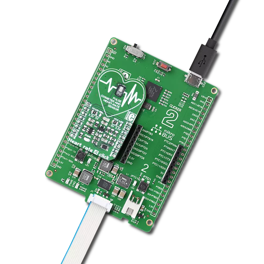
Heart Rate 4 Click is based on the MAX30101 high-sensitivity pulse oximeter and heart-rate sensor from Analog Devices. The click is designed to run on either 3.3V or 5V power supply. It communicates with the target MCU over the I2C interface, with additional functionality provided by the INT pin on the mikroBUS™ line. The MAX30101 is an integrated pulse oximetry and heart-rate monitor module. It includes internal LEDs, photodetectors, optical elements, and low-noise electronics with ambient light rejection. The MAX30101 integrates red, green, and IR
(infrared) LED drivers to modulate LED pulses for SpO2 and HR measurements. The LED current can be programmed from 0 to 50mA with proper supply voltage. The device includes a proximity function to save power and reduce visible light emission when the user's finger is not on the sensor. The MAX30101 has an on-chip temperature sensor for calibrating the temperature dependence of the SpO2 subsystem. The temperature sensor has an inherent resolution of 0.0625°C. Oxygen-saturated blood absorbs light differently than unsaturated blood. Pulse
oximeters measure the oxygen saturation in one's blood. Or, more precisely, the percentage of hemoglobin molecules in blood saturated with oxygen. These readings go from 94% to 100% in a healthy adult. Since oxygen-saturated blood absorbs more infrared light than red light, and unsaturated blood absorbs more red light than infrared light, the SpO2 readings are calculated by comparing the amount of these two types of light. It is best to use your finger for measurement.


Features overview
Development board
Clicker 2 for Kinetis is a compact starter development board that brings the flexibility of add-on Click boards™ to your favorite microcontroller, making it a perfect starter kit for implementing your ideas. It comes with an onboard 32-bit ARM Cortex-M4F microcontroller, the MK64FN1M0VDC12 from NXP Semiconductors, two mikroBUS™ sockets for Click board™ connectivity, a USB connector, LED indicators, buttons, a JTAG programmer connector, and two 26-pin headers for interfacing with external electronics. Its compact design with clear and easily recognizable silkscreen markings allows you to build gadgets with unique functionalities and
features quickly. Each part of the Clicker 2 for Kinetis development kit contains the components necessary for the most efficient operation of the same board. In addition to the possibility of choosing the Clicker 2 for Kinetis programming method, using a USB HID mikroBootloader or an external mikroProg connector for Kinetis programmer, the Clicker 2 board also includes a clean and regulated power supply module for the development kit. It provides two ways of board-powering; through the USB Micro-B cable, where onboard voltage regulators provide the appropriate voltage levels to each component on the board, or
using a Li-Polymer battery via an onboard battery connector. All communication methods that mikroBUS™ itself supports are on this board, including the well-established mikroBUS™ socket, reset button, and several user-configurable buttons and LED indicators. Clicker 2 for Kinetis is an integral part of the Mikroe ecosystem, allowing you to create a new application in minutes. Natively supported by Mikroe software tools, it covers many aspects of prototyping thanks to a considerable number of different Click boards™ (over a thousand boards), the number of which is growing every day.

Microcontroller Overview
MCU Card / MCU

Architecture
ARM Cortex-M4
MCU Memory (KB)
1024
Silicon Vendor
NXP
Pin count
121
RAM (Bytes)
262144
Used MCU Pins
mikroBUS™ mapper
Take a closer look
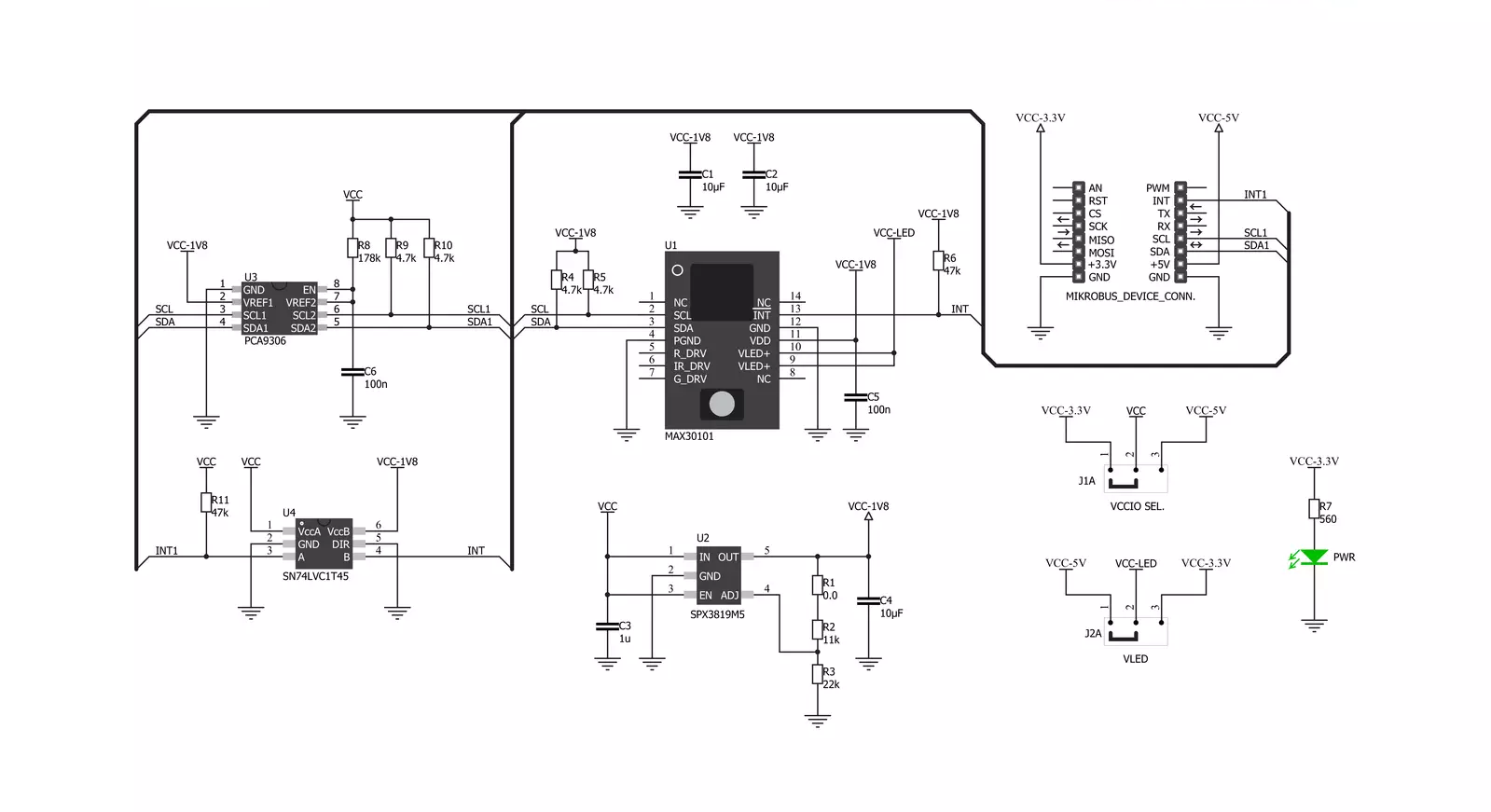
Click board™ Schematic
Step by step
Project assembly

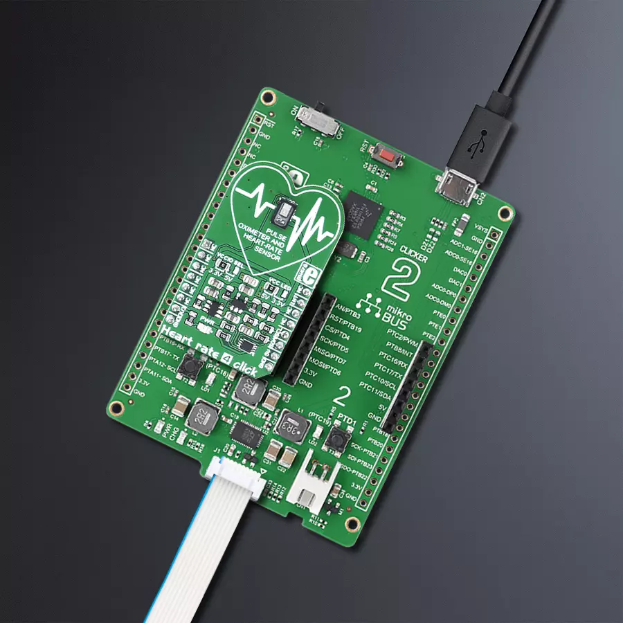
Start by selecting your development board and Click board™. Begin with the Clicker 2 for Kinetis as your development board.


Software Support
Library Description
This library contains API for Heart Rate 4 Click driver.
Key functions:
heartrate4_get_intrrupt- Function is used to read desired interrupt specified by flagheartrate4_get_red_val- Function is used to read the oldest RED valueheartrate4_enable_slot- Function is used to determine which LED is active in each time slot
Open Source
Code example
The complete application code and a ready-to-use project are available through the NECTO Studio Package Manager for direct installation in the NECTO Studio. The application code can also be found on the MIKROE GitHub account.
/*!
 * \file
 * \brief HeartRate4 Click example
 *
 * # Description
 * This example demonstrates the use of Heart rate 4 click board.
 *
 * The demo application is composed of two sections :
 *
 * ## Application Init
 * Initalizes I2C driver, applies default settings, and makes an initial log.
 *
 * ## Application Task
 * Reads data from Red diode and displays the results on USB UART if the measured data
 * is above defined threshold, otherwise, it displays desired message on the terminal.
 *
 *
 * \author MikroE Team
 *
 */
// ------------------------------------------------------------------- INCLUDES

#include "board.h"
#include "log.h"
#include "heartrate4.h"

// ------------------------------------------------------------------ VARIABLES

static heartrate4_t heartrate4;
static log_t logger;

static uint32_t red_samp = 0;
static uint8_t counter = 200;

// ------------------------------------------------------ APPLICATION FUNCTIONS

void application_init ( void )
{
    log_cfg_t log_cfg;
    heartrate4_cfg_t cfg;

    /**
     * Logger initialization.
     * Default baud rate: 115200
     * Default log level: LOG_LEVEL_DEBUG
     * @note If USB_UART_RX and USB_UART_TX
     * are defined as HAL_PIN_NC, you will
     * need to define them manually for log to work.
     * See @b LOG_MAP_USB_UART macro definition for detailed explanation.
     */
    LOG_MAP_USB_UART( log_cfg );
    log_init( &logger, &log_cfg );
    log_info( &logger, "---- Application Init ----" );

    //  Click initialization.

    heartrate4_cfg_setup( &cfg );
    HEARTRATE4_MAP_MIKROBUS( cfg, MIKROBUS_1 );
    heartrate4_init( &heartrate4, &cfg );

    Delay_ms( 100 );
    heartrate4_default_cfg( &heartrate4 );
    Delay_ms( 100 );
}

void application_task ( void )
{
    if ( heartrate4_get_intrrupt( &heartrate4, 1 ) & 0x40 )
    {
        red_samp = heartrate4_get_red_val( &heartrate4 );
        counter++;

        // If sample pulse amplitude is not under threshold value 0x8000
        if ( red_samp > 0x8000 )
        {
            log_printf( &logger, "%lu\r\n", red_samp );
            Delay_ms( 1 );
            counter = 200;
        }
        else if ( counter > 200 )
        {
            log_printf( &logger, "Place Finger On Sensor\r\n" );
            Delay_ms( 100 );
            counter = 0;
        }
    }
}

void main ( void )
{
    application_init( );

    for ( ; ; )
    {
        application_task( );
    }
}


// ------------------------------------------------------------------------ END
Additional Support
Resources
Category:Biometrics


