Keep your oxygen levels in check with MAX30102 and MK64FN1M0VDC12
Better health, better life
Published May 27, 2023
Click board™
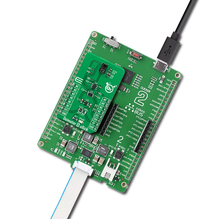
Oximeter 5 Click
Dev. board
Clicker 2 for Kinetis
Compiler
NECTO Studio
MCU
MK64FN1M0VDC12
Add optical pulse oximetry technology to your solution, enabling accurate and reliable blood oxygen saturation levels monitoring
A
A
Hardware Overview
How does it work?
Oximeter 5 Click is based on the MAX30102, a high-sensitivity pulse oximeter and heart-rate sensor from Maxim Integrated, now part of Analog Devices. The MAX30102 integrates Red and IR LEDs, with 660nm red and 880nm IR wavelengths, to modulate LED pulses for oxygen saturation (SpO2) and heart rate measurements. The LED pulse width can be programmed to allow the algorithm to optimize SpO2 and HR accuracy and power consumption based on use cases. The SpO2 subsystem of the MAX30102 contains ambient light cancellation (ALC), a continuous-time oversampling sigma-delta ADC with 18-bit resolution, and a proprietary discrete-time filter. The ALC has an internal Track/Hold circuit to cancel ambient light and increase the effective dynamic
range. The MAX30102 also has an on-chip temperature sensor with an inherent resolution of 0.0625°C for calibrating the temperature dependence of the SpO2 subsystem. The MAX30102 does not require a specific Power-Up sequence but requires a supply voltage of 1.8V to work correctly. Therefore, a small regulating LDO is used, the MAX8511, which provides a 1.8V out of selected 5V or 3.3V mikroBUS™ power rails. Also, it can be shut down through software with zero standby current, allowing the power rails to remain powered at all times. Oximeter 5 Click communicates with MCU using the standard I2C 2-Wire interface with a maximum clock frequency of 400kHz. It is fully adjustable through software registers, and the digital output data is stored in a 32-deep FIFO within the
device. Since the sensor for operation requires a power supply of 1.8V, this Click board™ also features the PCA9306and SN74LVC1T45voltage-level translators. The I2C interface bus lines are routed to the voltage-level translators allowing this Click board™ to work with both 3.3V and 5V MCUs properly. Also, it uses an interrupt pin, the INT pin of the mikroBUS™ socket, to alert the system that the MAX30102 is ready for operation. This Click board™ can operate with either 3.3V or 5V logic voltage levels selected via the VCC SEL jumper. This way, both 3.3V and 5V capable MCUs can use the communication lines properly. However, the Click board™ comes equipped with a library containing easy-to-use functions and an example code that can be used, as a reference, for further development.


Features overview
Development board
Clicker 2 for Kinetis is a compact starter development board that brings the flexibility of add-on Click boards™ to your favorite microcontroller, making it a perfect starter kit for implementing your ideas. It comes with an onboard 32-bit ARM Cortex-M4F microcontroller, the MK64FN1M0VDC12 from NXP Semiconductors, two mikroBUS™ sockets for Click board™ connectivity, a USB connector, LED indicators, buttons, a JTAG programmer connector, and two 26-pin headers for interfacing with external electronics. Its compact design with clear and easily recognizable silkscreen markings allows you to build gadgets with unique functionalities and
features quickly. Each part of the Clicker 2 for Kinetis development kit contains the components necessary for the most efficient operation of the same board. In addition to the possibility of choosing the Clicker 2 for Kinetis programming method, using a USB HID mikroBootloader or an external mikroProg connector for Kinetis programmer, the Clicker 2 board also includes a clean and regulated power supply module for the development kit. It provides two ways of board-powering; through the USB Micro-B cable, where onboard voltage regulators provide the appropriate voltage levels to each component on the board, or
using a Li-Polymer battery via an onboard battery connector. All communication methods that mikroBUS™ itself supports are on this board, including the well-established mikroBUS™ socket, reset button, and several user-configurable buttons and LED indicators. Clicker 2 for Kinetis is an integral part of the Mikroe ecosystem, allowing you to create a new application in minutes. Natively supported by Mikroe software tools, it covers many aspects of prototyping thanks to a considerable number of different Click boards™ (over a thousand boards), the number of which is growing every day.

Microcontroller Overview
MCU Card / MCU

Architecture
ARM Cortex-M4
MCU Memory (KB)
1024
Silicon Vendor
NXP
Pin count
121
RAM (Bytes)
262144
Used MCU Pins
mikroBUS™ mapper
Take a closer look
Click board™ Schematic

Step by step
Project assembly

Start by selecting your development board and Click board™. Begin with the Clicker 2 for Kinetis as your development board.


Software Support
Library Description
This library contains API for Oximeter 5 Click driver.
Key functions:
oximeter5_read_sensor_dataOximeter 5 get sensor data function.oximeter5_get_oxygen_saturationOximeter 5 get oxygen saturation function.oximeter5_read_temperatureOximeter 5 read temperature function.
Open Source
Code example
The complete application code and a ready-to-use project are available through the NECTO Studio Package Manager for direct installation in the NECTO Studio. The application code can also be found on the MIKROE GitHub account.
/*!
 * @file main.c
 * @brief Oximeter5 Click example
 *
 * # Description
 * This library contains API for Oximeter 5 Click driver.
 * The demo application reads and calculate
 * SpO2 oxygen saturation data.
 *
 * The demo application is composed of two sections :
 *
 * ## Application Init
 * Initializes I2C driver and log UART.
 * After driver initialization the app set
 * driver interface setup and  default settings,
 * buffer length of 100 stores 4 seconds of samples running at 25sps
 * read the first 100 samples, and determine the signal range.
 *
 * ## Application Task
 * This is an example that demonstrates the use of the Oximeter 5 Click board™.
 * In this example, display the IR and RED ADC data,
 * and the SpO2 oxygen saturation data [ 0% - 100% ].
 * Results are being sent to the Usart Terminal where you can track their changes.
 *
 * @note
 * A measurement time of at least 10 seconds is required
 * for the SpO2 oxygen saturation data to be valid.
 *
 * @author Nenad Filipovic
 *
 */

#include "board.h"
#include "log.h"
#include "oximeter5.h"

static oximeter5_t oximeter5;
static log_t logger;
static uint32_t aun_ir_buffer[ 100 ];
static uint32_t aun_red_buffer[ 100 ];
static uint32_t un_min, un_max, un_prev_data, un_brightness;
static float f_temp;
static uint8_t n_spo2;

void application_init ( void )
{
    log_cfg_t log_cfg;              /**< Logger config object. */
    oximeter5_cfg_t oximeter5_cfg;  /**< Click config object. */

    /**
     * Logger initialization.
     * Default baud rate: 115200
     * Default log level: LOG_LEVEL_DEBUG
     * @note If USB_UART_RX and USB_UART_TX
     * are defined as HAL_PIN_NC, you will
     * need to define them manually for log to work.
     * See @b LOG_MAP_USB_UART macro definition for detailed explanation.
     */
    LOG_MAP_USB_UART( log_cfg );
    log_init( &logger, &log_cfg );
    log_info( &logger, " Application Init " );

    // Click initialization.
    oximeter5_cfg_setup( &oximeter5_cfg );
    OXIMETER5_MAP_MIKROBUS( oximeter5_cfg, MIKROBUS_1 );
    if ( I2C_MASTER_ERROR == oximeter5_init( &oximeter5, &oximeter5_cfg ) )
    {
        log_error( &logger, " Communication init." );
        for ( ; ; );
    }
    Delay_ms ( 100 );

    if ( OXIMETER5_ERROR == oximeter5_default_cfg ( &oximeter5 ) )
    {
        log_error( &logger, " Default configuration." );
        for ( ; ; );
    }
    Delay_ms ( 100 );

    un_brightness = 0;
    un_min = 0x3FFFF;
    un_max = 0;

    for ( uint8_t n_cnt = 0; n_cnt < 100; n_cnt++ )
    {
        while ( oximeter5_check_interrupt( &oximeter5 ) == OXIMETER5_INTERRUPT_ACTIVE );

        oximeter5_read_sensor_data( &oximeter5, &aun_red_buffer[ n_cnt ], &aun_ir_buffer[ n_cnt ] );

        if ( un_min > aun_red_buffer[ n_cnt ] )
        {
            un_min = aun_red_buffer[ n_cnt ];
        }

        if ( un_max < aun_red_buffer[ n_cnt ] )
        {
            un_max = aun_red_buffer[ n_cnt ];
        }
    }

    oximeter5_get_oxygen_saturation( &aun_ir_buffer[ 0 ], 100, &aun_red_buffer[ 0 ], &n_spo2 );
    log_info( &logger, " Application Task " );
    Delay_ms ( 100 );
}

void application_task ( void )
{
    for ( uint8_t n_cnt = 25; n_cnt < 100; n_cnt++ )
    {
        aun_red_buffer[ n_cnt - 25 ] = aun_red_buffer[ n_cnt ];
        aun_ir_buffer[ n_cnt - 25 ] = aun_ir_buffer[ n_cnt ];

        if ( un_min > aun_red_buffer[ n_cnt ] )
        {
            un_min = aun_red_buffer[ n_cnt ];
        }

        if ( un_max < aun_red_buffer[ n_cnt ] )
        {
            un_max=aun_red_buffer[n_cnt];
        }
    }

    for ( uint8_t n_cnt = 75; n_cnt < 100; n_cnt++ )
    {
        un_prev_data = aun_red_buffer[ n_cnt - 1 ];
        while ( oximeter5_check_interrupt( &oximeter5 ) == OXIMETER5_INTERRUPT_ACTIVE );

        oximeter5_read_sensor_data( &oximeter5, &aun_red_buffer[ n_cnt ], &aun_ir_buffer[ n_cnt ] );

        if ( aun_red_buffer[ n_cnt ] > un_prev_data )
        {
            f_temp = aun_red_buffer[ n_cnt ]-un_prev_data;
            f_temp /= ( un_max - un_min );
            f_temp *= MAX_BRIGHTNESS;
            f_temp = un_brightness - f_temp;

            if ( f_temp < 0 )
            {
                un_brightness = 0;
            }
            else
            {
                un_brightness = ( uint32_t ) f_temp;
            }
        }
        else
        {
            f_temp = un_prev_data - aun_red_buffer[ n_cnt ];
            f_temp /= ( un_max - un_min );
            f_temp *= MAX_BRIGHTNESS;
            un_brightness += ( uint32_t ) f_temp;

            if ( un_brightness > MAX_BRIGHTNESS )
            {
                un_brightness = MAX_BRIGHTNESS;
            }
        }

        if ( ( OXIMETER5_OK == oximeter5_get_oxygen_saturation( &aun_ir_buffer[ 0 ], 100, &aun_red_buffer[ 0 ], &n_spo2 ) ) )
        {
            if ( aun_ir_buffer[n_cnt] > 10000  )
            {
                log_printf( &logger, "\tIR    : %lu \r\n", aun_ir_buffer[ n_cnt ] );
                log_printf( &logger, "\tRED   : %lu \r\n", aun_red_buffer[ n_cnt ] );
                log_printf( &logger, "- - - - - - - - - - - - - - -\r\n" );
                log_printf( &logger, "\tSPO2  : %d %%\r\n", ( uint16_t ) n_spo2 );
                log_printf( &logger, "-----------------------------\r\n" );
                Delay_ms ( 100 );
            }
            else
            {
                Delay_ms ( 10 );
            }
        }
    }
}

int main ( void )
{
    /* Do not remove this line or clock might not be set correctly. */
    #ifdef PREINIT_SUPPORTED
    preinit();
    #endif

    application_init( );

    for ( ; ; )
    {
        application_task( );
    }

    return 0;
}

// ------------------------------------------------------------------------ END
Additional Support
Resources
Category:Biometrics


