Improve your AC measurement with MCP3201 and MK64FN1M0VDC12
Flawless AC insight at your fingertips
Published Aug 10, 2023
Click board™
AC Current Click
Dev. board
Clicker 2 for Kinetis
Compiler
NECTO Studio
MCU
MK64FN1M0VDC12
Harness our advanced AC measurement solution to optimize power usage, enhance safety, and elevate efficiency across diverse applications
A
A
Hardware Overview
How does it work?
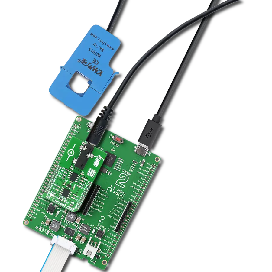
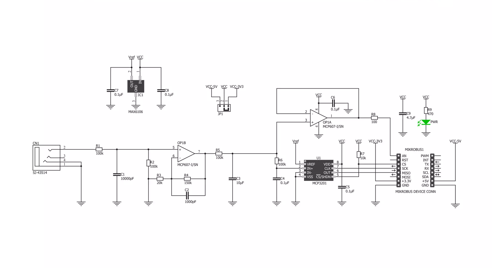
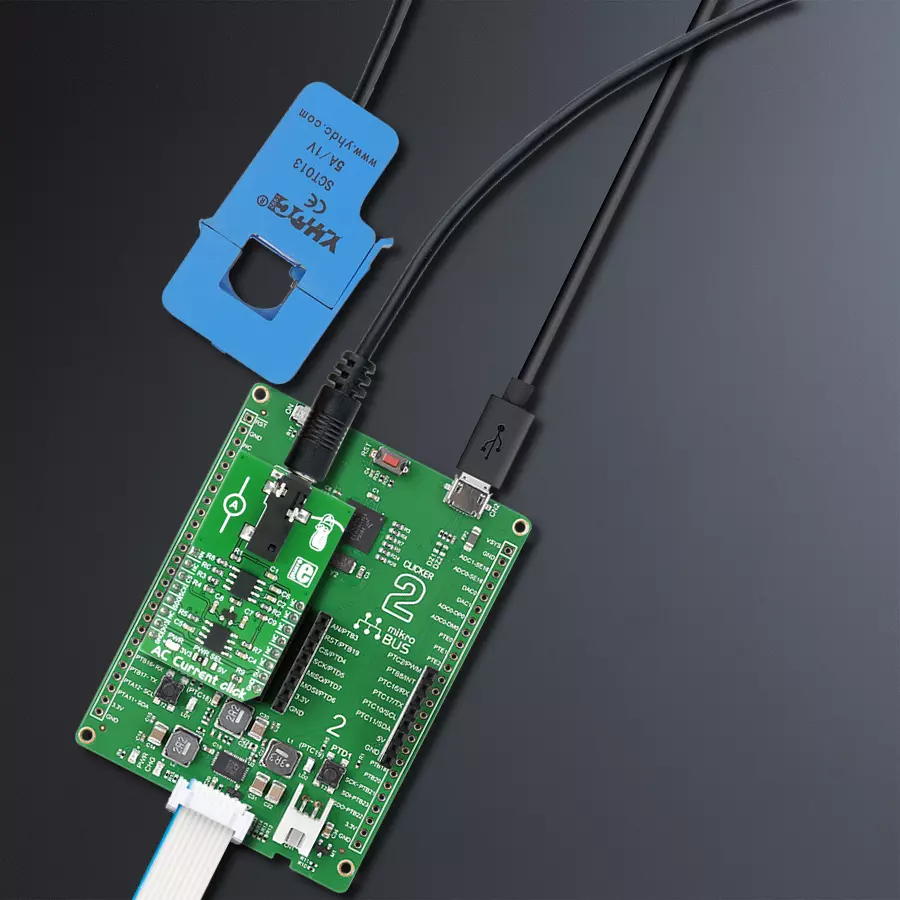
AC Current Click is based on the MCP607, a micropower CMOS operational amplifier from Microchip. The non-invasive sensor that should be used along this Click board™ works by utilizing the electromagnetic induction phenomenon, similar to a transformer. The primary coil does not exist, though; the electromagnetic field is generated by the AC Current running through the cable, which is measured. The core of the sensing probe is split, allowing it to clamp on the current conducting cable. Since the sensor does not influence the measurement circuitry in any way while being galvanically isolated simultaneously, it is an ideal solution to measure current running through mains or similar high-voltage installations. Note that only the AC current can be measured since the DC current cannot generate the alternating magnetic field, so the sensor can only be used for the AC current measurement. The Click board™ comes equipped with the 3.5mm jack connector, which is used to attach the sensing probe. The sensor input is filtered and amplified over the MCP607 so that the readings can stay reliable and protected against EMI and radio interference. The reference voltage for the conversion is 2.048V, and the MAX6106, a voltage reference from Analog Devices
provides it. It samples the input voltage generated by the contactless, non-invasive current sensor attached to the 3.5mm jack connector. This allows a minimal distortion of the input. The amplification ratio (G) is calculated using the non-inverting operational amplifier configuration formula: G = 1 + R4 / R3. Knowing the maximum voltage of the sensor (for 10A current), the reference voltage of 2.048V for the ADC, and the gain factor of the op-amp, it is easy to calculate the value for the measured current. The Click board™ comes with library functions that do all the necessary calculations, providing a simple and quick solution for application development. A user can also easily develop his methods and functions using existing ones if some other sensor with different nominal values is used. However, this Click board™ also comes as part of the AC Current click - bundle, which also contains the current measuring sensor calibrated and well suited to work with the AC Current click (10A - 1V). AC Current Click uses a standard 3-Wire (read-only) SPI serial interface of the MCP3201 to communicate with the host MCU. Besides the onboard A/D converter, an analog signal path is available to the users, allowing the board™ to fit into various usage scenarios. Besides
the onboard ADC, it is possible to use an external converter by using the AN pin of the mikroBUS™. The preconditioned voltage from the first (non-inverting) operational amplifier is routed to the onboard ADC and another op-amp, which acts as the buffer with unity gain. It provides a buffered analog voltage at the AN pin, which can be used externally, bypassing the onboard ADC. The MCP607 consists of two integrated op-amps, so the same IC is used both for the input preconditioning and the output buffer. Note that although the Click board™ is meant to measure current without making contact using a galvanically isolated sensor over an isolated cable, special care should always be taken when working with dangerous voltages. Any operation which involves high voltage should be performed by trained personnel. This Click board™ can operate with either 3.3V or 5V logic levels selected via the VCC SEL jumper. This way, both 3.3V and 5V capable MCUs can use the communication lines properly. Also, this Click board™ comes equipped with a library containing easy-to-use functions and an example code that can be used, as a reference, for further development.


Features overview
Development board
Clicker 2 for Kinetis is a compact starter development board that brings the flexibility of add-on Click boards™ to your favorite microcontroller, making it a perfect starter kit for implementing your ideas. It comes with an onboard 32-bit ARM Cortex-M4F microcontroller, the MK64FN1M0VDC12 from NXP Semiconductors, two mikroBUS™ sockets for Click board™ connectivity, a USB connector, LED indicators, buttons, a JTAG programmer connector, and two 26-pin headers for interfacing with external electronics. Its compact design with clear and easily recognizable silkscreen markings allows you to build gadgets with unique functionalities and
features quickly. Each part of the Clicker 2 for Kinetis development kit contains the components necessary for the most efficient operation of the same board. In addition to the possibility of choosing the Clicker 2 for Kinetis programming method, using a USB HID mikroBootloader or an external mikroProg connector for Kinetis programmer, the Clicker 2 board also includes a clean and regulated power supply module for the development kit. It provides two ways of board-powering; through the USB Micro-B cable, where onboard voltage regulators provide the appropriate voltage levels to each component on the board, or
using a Li-Polymer battery via an onboard battery connector. All communication methods that mikroBUS™ itself supports are on this board, including the well-established mikroBUS™ socket, reset button, and several user-configurable buttons and LED indicators. Clicker 2 for Kinetis is an integral part of the Mikroe ecosystem, allowing you to create a new application in minutes. Natively supported by Mikroe software tools, it covers many aspects of prototyping thanks to a considerable number of different Click boards™ (over a thousand boards), the number of which is growing every day.

Microcontroller Overview
MCU Card / MCU

Architecture
ARM Cortex-M4
MCU Memory (KB)
1024
Silicon Vendor
NXP
Pin count
121
RAM (Bytes)
262144
You complete me!
Accessories
The AC Current sensor is a non-invasive device designed for measuring alternating current. This split-core sensor can easily clip around live or neutral wires, making it versatile for various applications. It finds utility in the current measurement, monitoring, and protection of AC motors, lighting equipment, and air compressors. Key features of this sensor include an open size of 13mm x 13mm, a leading wire length of 1m, and a dielectric strength of 1000V AC/1min 5mA between the shell and output. It operates within a temperature range of -25°C to +70°C, adhering to a resistance grade of Grade B. The built-in sampling resistance (RL) is 186Ω, boasting a non-linearity of ±3%. The output mode ranges from 0 to 1V, accommodating input currents from 0 to 10A AC. With a fire resistance property in accordance with UL94-VO, this AC Current sensor ensures reliable and safe current monitoring in diverse electrical applications.

Used MCU Pins
mikroBUS™ mapper
Take a closer look
Click board™ Schematic
Step by step
Project assembly

Start by selecting your development board and Click board™. Begin with the Clicker 2 for Kinetis as your development board.


Software Support
Library Description
This library contains API for AC Current Click driver.
Key functions:
accurrent_get_a- Gets current value of AC Current in Aaccurrent_get_ma- Gets current value of AC Current in mA.
Open Source
Code example
The complete application code and a ready-to-use project are available through the NECTO Studio Package Manager for direct installation in the NECTO Studio. The application code can also be found on the MIKROE GitHub account.
/*!
 * \file
 * \brief AcCurrent Click example
 *
 * # Description
 * This application measures AC current through a conductor.
 *
 * The demo application is composed of two sections :
 *
 * ## Application Init
 * SPI driver and Click initialization.
 *
 * ## Application Task
 * Reads the value of AC current and displays it on the USB UART.
 *
 * ## NOTE
 * An appropriate AC Current sensor needs to be connected to the Click board.
 *
 * \author MikroE Team
 *
 */
// ------------------------------------------------------------------- INCLUDES

#include "board.h"
#include "log.h"
#include "accurrent.h"

// ------------------------------------------------------------------ VARIABLES

static accurrent_t accurrent;
static log_t logger;

void application_init ( void )
{
    log_cfg_t log_cfg;
    accurrent_cfg_t cfg;

    /**
     * Logger initialization.
     * Default baud rate: 115200
     * Default log level: LOG_LEVEL_DEBUG
     * @note If USB_UART_RX and USB_UART_TX
     * are defined as HAL_PIN_NC, you will
     * need to define them manually for log to work.
     * See @b LOG_MAP_USB_UART macro definition for detailed explanation.
     */
    LOG_MAP_USB_UART( log_cfg );
    log_init( &logger, &log_cfg );
    log_info( &logger, "---- Application Init ----" );

    //  Click initialization.
    accurrent_cfg_setup( &cfg );
    ACCURRENT_MAP_MIKROBUS( cfg, MIKROBUS_1 );
    accurrent_init( &accurrent, &cfg );
}

void application_task ( void )
{
    float ac_current = 0;
    ac_current = accurrent_get_ma( &accurrent );
    log_printf( &logger, "Current value: %.3f mA\r\n", ac_current );
    Delay_ms ( 1000 );
}

int main ( void )
{
    /* Do not remove this line or clock might not be set correctly. */
    #ifdef PREINIT_SUPPORTED
    preinit();
    #endif

    application_init( );

    for ( ; ; )
    {
        application_task( );
    }

    return 0;
}


// ------------------------------------------------------------------------ END
Additional Support
Resources
Category:Current sensor


