Attain thermal imaging and object detection with AMG883543 and PIC18F4550
Infrared array Grid-EYE sensor for temperature detection of tw-dimensional area
Published Sep 03, 2024
Click board™
Grid-EYE 2 Click
Dev. board
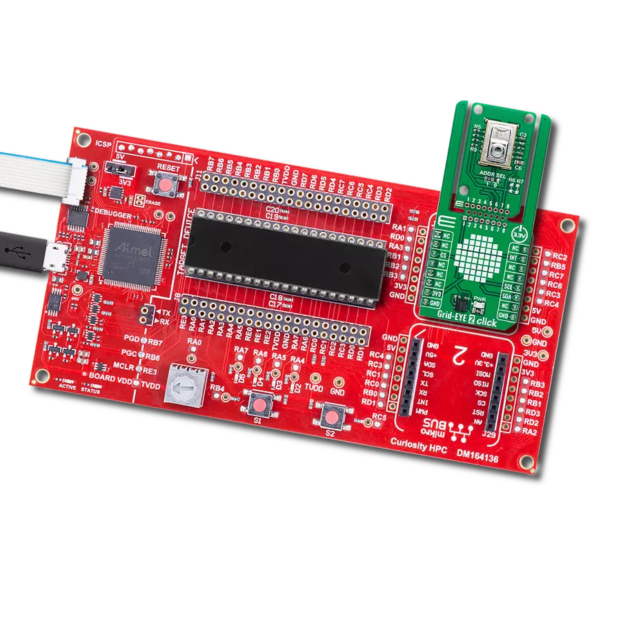
Curiosity HPC
Compiler
NECTO Studio
MCU
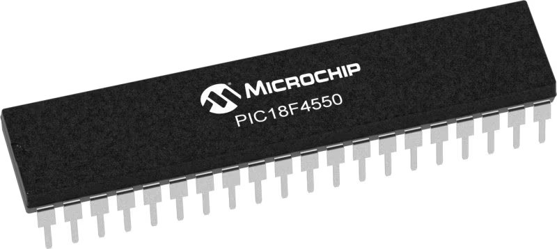
PIC18F4550
Detect and measure temperature variations while identifying moving objects based on those changes
A
A
Hardware Overview
How does it work?
Grid-EYE 2 Click is based on the AMG883543, an infrared array sensor from Panasonic with a 90° viewing angle. It captures temperature data across a two-dimensional 8x8 matrix (64 pixels) and provides this information as a digital output. Each pixel measures temperatures ranging from 0°C to 80°C with a resolution of 0.25°C, allowing the detection of objects at distances up to 5 meters. With its ability to create thermal images and detect movement, Grid-EYE 2 Click is ideal for developing thermal imaging systems, monitoring people and objects, enhancing high-performance home appliances (like microwave ovens and air conditioners), promoting energy efficiency in offices (through air-conditioning and lighting controls), and applications in digital signage, automatic doors,
elevators, and more. This Click board™ is designed in a unique format supporting the newly introduced MIKROE feature called "Click Snap." Unlike the standardized version of Click boards, this feature allows the main sensor area to become movable by breaking the PCB, opening up many new possibilities for implementation. Thanks to the Snap feature, the AMG883543 can operate autonomously by accessing its signals directly on the pins marked 1-8. Additionally, the Snap part includes a specified and fixed screw hole position, enabling users to secure the Snap board in their desired location. Grid-EYE 2 Click uses a standard 2-wire I2C interface to communicate with the host MCU, supporting Standard mode with up to 400kHz of frequency clock. In addition to the I2C interface
pins, this board also uses an interrupt (INT) pin and a jumper for I2C address selection, ADDR SEL. The interrupt pin can signal the host MCU when a specific condition is met, such as when the temperature in any of the sensor's pixels exceeds a predefined threshold. This allows the system to respond immediately to changes in temperature without constantly polling the sensor, thereby saving processing power and energy. This Click board™ can be operated only with a 3.3V logic voltage level. The board must perform appropriate logic voltage level conversion before using MCUs with different logic levels. Also, it comes equipped with a library containing functions and an example code that can be used as a reference for further development.

Features overview
Development board
Curiosity HPC, standing for Curiosity High Pin Count (HPC) development board, supports 28- and 40-pin 8-bit PIC MCUs specially designed by Microchip for the needs of rapid development of embedded applications. This board has two unique PDIP sockets, surrounded by dual-row expansion headers, allowing connectivity to all pins on the populated PIC MCUs. It also contains a powerful onboard PICkit™ (PKOB), eliminating the need for an external programming/debugging tool, two mikroBUS™ sockets for Click board™ connectivity, a USB connector, a set of indicator LEDs, push button switches and a variable potentiometer. All
these features allow you to combine the strength of Microchip and Mikroe and create custom electronic solutions more efficiently than ever. Each part of the Curiosity HPC development board contains the components necessary for the most efficient operation of the same board. An integrated onboard PICkit™ (PKOB) allows low-voltage programming and in-circuit debugging for all supported devices. When used with the MPLAB® X Integrated Development Environment (IDE, version 3.0 or higher) or MPLAB® Xpress IDE, in-circuit debugging allows users to run, modify, and troubleshoot their custom software and hardware
quickly without the need for additional debugging tools. Besides, it includes a clean and regulated power supply block for the development board via the USB Micro-B connector, alongside all communication methods that mikroBUS™ itself supports. Curiosity HPC development board allows you to create a new application in just a few steps. Natively supported by Microchip software tools, it covers many aspects of prototyping thanks to many number of different Click boards™ (over a thousand boards), the number of which is growing daily.

Microcontroller Overview
MCU Card / MCU
Architecture
PIC
MCU Memory (KB)
32
Silicon Vendor
Microchip
Pin count
40
RAM (Bytes)
2048
Used MCU Pins
mikroBUS™ mapper
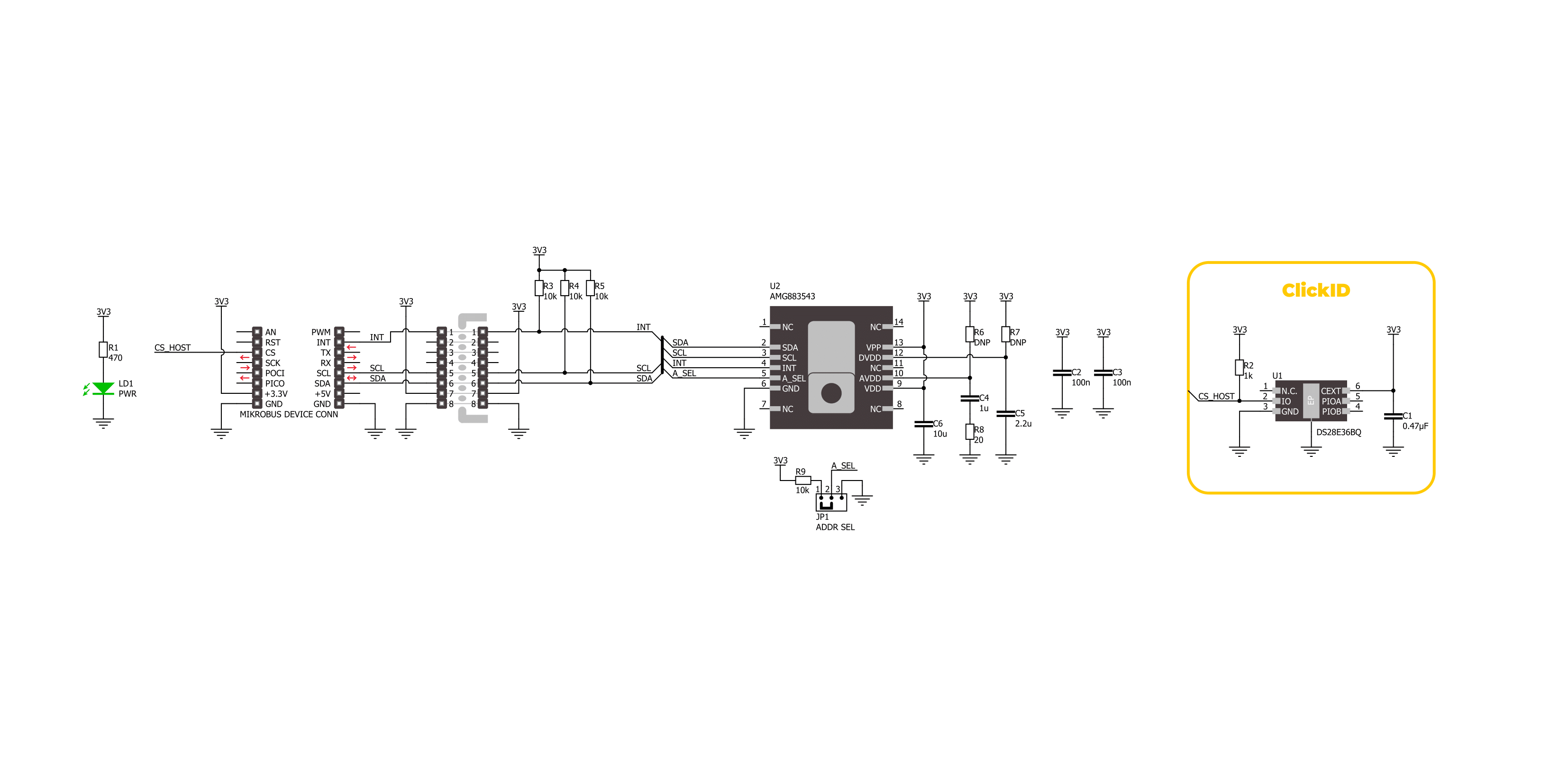
Take a closer look
Click board™ Schematic
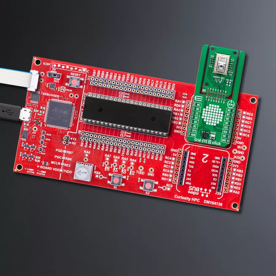
Step by step
Project assembly

Start by selecting your development board and Click board™. Begin with the Curiosity HPC as your development board.


Software Support
Library Description
This library contains API for Grid-EYE 2 Click driver.
Key functions:
grideye2_get_int_pin- This function returns the INT pin logic state.grideye2_read_grid- This function reads the temperature measurement of an 8x8 pixels grid and stores it in the ctx->grid_temp array.grideye2_clear_status- This function clears the interrupt status flags.
Open Source
Code example
The complete application code and a ready-to-use project are available through the NECTO Studio Package Manager for direct installation in the NECTO Studio. The application code can also be found on the MIKROE GitHub account.
/*!
 * @file main.c
 * @brief Grid-EYE 2 Click example
 *
 * # Description
 * This example demonstrates the use of Grid-EYE 2 Click by reading and displaying
 * the temperature measurements as an 8x8 pixels grid.
 *
 * The demo application is composed of two sections :
 *
 * ## Application Init
 * Initializes the driver and performs the Click default configuration which enables
 * the data ready interrupt and sets data measurement to 10 frames per second.
 *
 * ## Application Task
 * Waits for a data ready interrupt and then reads the grid temperature measurements
 * and displays the results on the USB UART in a form of an 8x8 pixels grid.
 *
 * @author Stefan Filipovic
 *
 */

#include "board.h"
#include "log.h"
#include "grideye2.h"

static grideye2_t grideye2;
static log_t logger;

void application_init ( void )
{
    log_cfg_t log_cfg;  /**< Logger config object. */
    grideye2_cfg_t grideye2_cfg;  /**< Click config object. */

    /**
     * Logger initialization.
     * Default baud rate: 115200
     * Default log level: LOG_LEVEL_DEBUG
     * @note If USB_UART_RX and USB_UART_TX
     * are defined as HAL_PIN_NC, you will
     * need to define them manually for log to work.
     * See @b LOG_MAP_USB_UART macro definition for detailed explanation.
     */
    LOG_MAP_USB_UART( log_cfg );
    log_init( &logger, &log_cfg );
    log_info( &logger, " Application Init " );

    // Click initialization.
    grideye2_cfg_setup( &grideye2_cfg );
    GRIDEYE2_MAP_MIKROBUS( grideye2_cfg, MIKROBUS_1 );
    if ( I2C_MASTER_ERROR == grideye2_init( &grideye2, &grideye2_cfg ) )
    {
        log_error( &logger, " Communication init." );
        for ( ; ; );
    }

    if ( GRIDEYE2_ERROR == grideye2_default_cfg ( &grideye2 ) )
    {
        log_error( &logger, " Default configuration." );
        for ( ; ; );
    }

    log_info( &logger, " Application Task " );
}

void application_task ( void )
{
    // Wait for data ready interrupt
    while ( grideye2_get_int_pin ( &grideye2 ) );

    if ( GRIDEYE2_OK == grideye2_read_grid ( &grideye2 ) )
    {
        grideye2_clear_status ( &grideye2 );
        for ( uint8_t cnt = 0; cnt < GRIDEYE2_NUM_PIXELS; cnt++ )
        {
            if ( 0 == ( cnt % 8 ) )
            {
                log_printf( &logger, "\r\n" );
            }
            log_printf( &logger, "%.2f ", grideye2.grid_temp[ cnt ] );
        }
        log_printf( &logger, "\r\n" );
    }
}

int main ( void )
{
    /* Do not remove this line or clock might not be set correctly. */
    #ifdef PREINIT_SUPPORTED
    preinit();
    #endif

    application_init( );

    for ( ; ; )
    {
        application_task( );
    }

    return 0;
}

// ------------------------------------------------------------------------ END
Additional Support
Resources
Category:Temperature & humidity


