Experience Bluetooth like never before with BGX13S22GA-V31 and PIC18F4525
Connecting possibilities, empowering lifestyles
Published Nov 01, 2023
Click board™
BLE 7 Click
Dev. board
Curiosity HPC
Compiler
NECTO Studio
MCU
PIC18F4525
Say goodbye to tangled wires and embrace a world of simplified connectivity, empowering you to stream, share, and control your devices effortlessly
A
A
Hardware Overview
How does it work?
BLE 7 Click is based on the BGX13S22GA-V31, a module from Silicon Labs that has some impressive features, including the fact that it is Bluetooth 5 low energy compliant, GPIO control through command API, Encrypted bonding and connectivity, and an Integrated DC-DC Converter. The BGX13S22GA-V31 module eliminates Bluetooth firmware development complexity with a serial interface that can operate as a raw data stream or control the device through an abstracted command API. The BGX13S22GA-V31 can facilitate a device-to-device cable replacement link or communicate with mobile devices through the Xpress Bluetooth mobile library. The device integrates a Bluetooth 5-compliant stack to future-proof applications as Bluetooth 5 adoption increases. The device is targeted for applications
where ultra-small size, reliable, high-performance RF, low power consumption, and fast time-to-market are key requirements. BGX13S22GA-V31 also integrates a high-performance, ultra-robust antenna, which requires minimal PCB, plastic, and metal clearance. Unless stated otherwise, minimum and maximum values represent the worst conditions across supply voltage, process variation, and operating temperature. The BGX13S module has only one external supply pin (VDD). Several internal supply rails are mentioned in the electrical specifications, whose connections vary based on transmit power configuration. The BGX13S creates a Bluetooth five-compliant BLE cable replacement interface, facilitating a BLE link to a second embedded or mobile device. An embedded MCU controls the device and
communicates across the BLE link through a serial interface and control signals. Parameters stored in non-volatile memory and configurable through the serial interface adjust the device's performance characteristics. Silicon Labs offers iOS and Android mobile libraries for Blue Gecko Xpress devices to speed mobile development and simplify communication. This Click board™ can be operated only with a 3.3V logic voltage level. The board must perform appropriate logic voltage level conversion before using MCUs with different logic levels. Also, it comes equipped with a library containing functions and an example code that can be used, as a reference, for further development.


Features overview
Development board
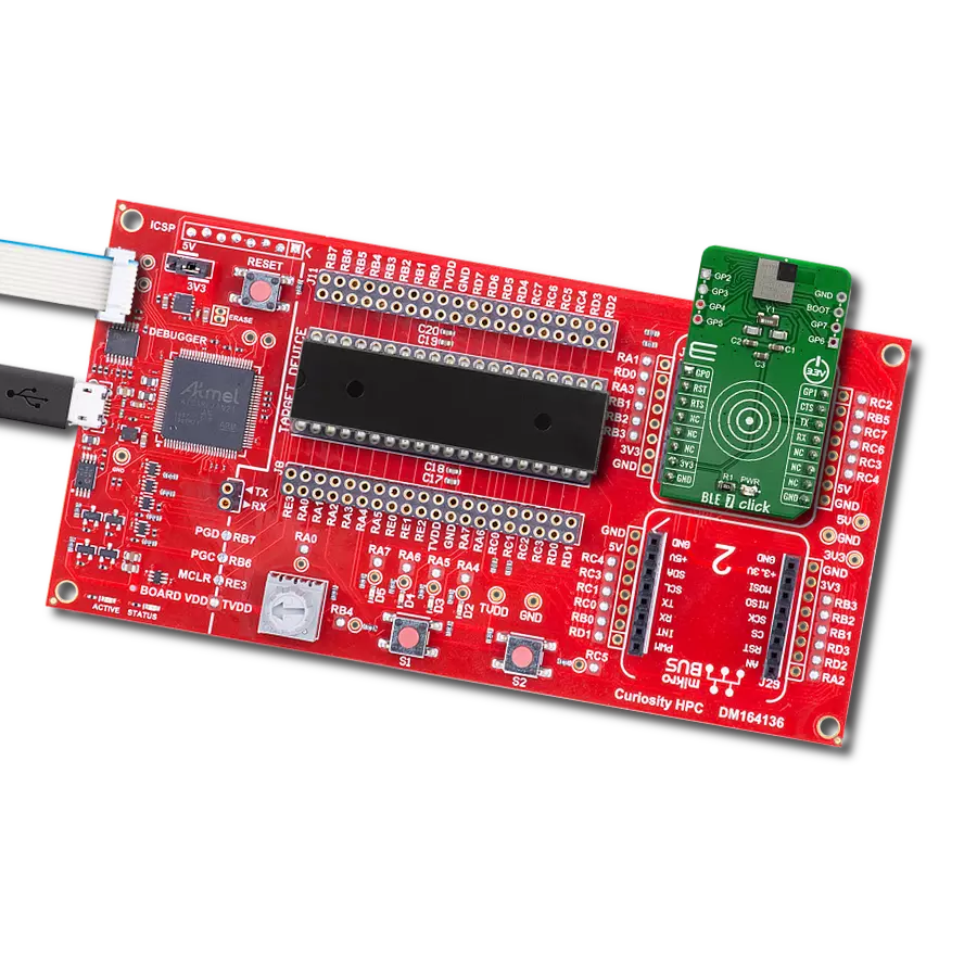
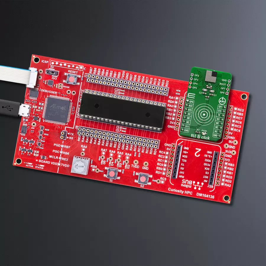
Curiosity HPC, standing for Curiosity High Pin Count (HPC) development board, supports 28- and 40-pin 8-bit PIC MCUs specially designed by Microchip for the needs of rapid development of embedded applications. This board has two unique PDIP sockets, surrounded by dual-row expansion headers, allowing connectivity to all pins on the populated PIC MCUs. It also contains a powerful onboard PICkit™ (PKOB), eliminating the need for an external programming/debugging tool, two mikroBUS™ sockets for Click board™ connectivity, a USB connector, a set of indicator LEDs, push button switches and a variable potentiometer. All
these features allow you to combine the strength of Microchip and Mikroe and create custom electronic solutions more efficiently than ever. Each part of the Curiosity HPC development board contains the components necessary for the most efficient operation of the same board. An integrated onboard PICkit™ (PKOB) allows low-voltage programming and in-circuit debugging for all supported devices. When used with the MPLAB® X Integrated Development Environment (IDE, version 3.0 or higher) or MPLAB® Xpress IDE, in-circuit debugging allows users to run, modify, and troubleshoot their custom software and hardware
quickly without the need for additional debugging tools. Besides, it includes a clean and regulated power supply block for the development board via the USB Micro-B connector, alongside all communication methods that mikroBUS™ itself supports. Curiosity HPC development board allows you to create a new application in just a few steps. Natively supported by Microchip software tools, it covers many aspects of prototyping thanks to many number of different Click boards™ (over a thousand boards), the number of which is growing daily.

Microcontroller Overview
MCU Card / MCU

Architecture
PIC
MCU Memory (KB)
48
Silicon Vendor
Microchip
Pin count
40
RAM (Bytes)
3968
Used MCU Pins
mikroBUS™ mapper
Take a closer look
Click board™ Schematic

Step by step
Project assembly

Start by selecting your development board and Click board™. Begin with the Curiosity HPC as your development board.


Software Support
Library Description
This library contains API for BLE 7 Click driver.
Key functions:
ble7_reset- This function allows user to reset BGX moduleble7_send_command- This function allows user to transmit data to the BGX module
Open Source
Code example
The complete application code and a ready-to-use project are available through the NECTO Studio Package Manager for direct installation in the NECTO Studio. The application code can also be found on the MIKROE GitHub account.
/*!
 * \file
 * \brief Ble7 Click example
 *
 * # Description
 * This example reads and processes data from BLE 7 Clicks.
 *
 * The demo application is composed of two sections :
 *
 * ## Application Init
 * Initializes the driver and configures the Click board.
 *
 * ## Application Task
 * Checks for the received data, reads it and replies with a certain message.
 *
 * ## Additional Function
 * - ble7_process ( ) - Logs all received messages on UART, and sends the certain message back
 * to the connected device.
 *
 * @note
 * We have used the BLE Scanner smartphone application for the test.
 * A smartphone and the Click board must be paired in order to exchange messages with each other.
 * For more information about the BGX module commands, please refer to the following link:
 * https://docs.silabs.com/gecko-os/1/bgx/latest/commands
 *
 * \author MikroE Team
 *
 */
// ------------------------------------------------------------------- INCLUDES

#include "board.h"
#include "log.h"
#include "ble7.h"
#include "string.h"

#define PROCESS_COUNTER 10
#define PROCESS_RX_BUFFER_SIZE 200

// ------------------------------------------------------------------ VARIABLES

#define BLE7_ENABLE_ECHO                        "set sy c e 1"
#define BLE7_CLEAR_BONDING                      "clrb"
#define BLE7_ENABLE_BONDING                     "set bl e b 1"
#define BLE7_ENABLE_PAIRING                     "set bl e p any"
#define BLE7_SET_ADVERTISING_ON                 "adv high"
#define BLE7_SET_ADVERTISING_HIGH_DURATION      "set bl v h d 120"
#define BLE7_SET_DEVICE_NAME                    "set sy d n \"BLE7-DEVICE\""
#define BLE7_SAVE_CONFIGURATION                 "save"
#define BLE7_SWITCH_TO_STREAM_MODE              "str"

static ble7_t ble7;
static log_t logger;
static uint8_t data_mode = 0;
static uint8_t config_mode = 0;
static char current_parser_buf[ PROCESS_RX_BUFFER_SIZE ];

// ------------------------------------------------------- ADDITIONAL FUNCTIONS

static int8_t ble7_process ( void )
{
    int32_t rsp_size;
    uint16_t rsp_cnt = 0;
    int8_t ret_flag = 0;

    char uart_rx_buffer[ PROCESS_RX_BUFFER_SIZE ] = { 0 };
    uint8_t check_buf_cnt;
    uint8_t process_cnt = PROCESS_COUNTER;

    // Clear current buffer
    memset( current_parser_buf, 0, PROCESS_RX_BUFFER_SIZE );

    while( process_cnt != 0 )
    {
        rsp_size = ble7_generic_read( &ble7, uart_rx_buffer, PROCESS_RX_BUFFER_SIZE );

        if ( rsp_size > 0 )
        {
            // Validation of the received data
            for ( check_buf_cnt = 0; check_buf_cnt < rsp_size; check_buf_cnt++ )
            {
                if ( uart_rx_buffer[ check_buf_cnt ] == 0 )
                {
                    uart_rx_buffer[ check_buf_cnt ] = 13;
                }
            }
            // Storages data in current buffer
            rsp_cnt += rsp_size;
            if ( rsp_cnt < PROCESS_RX_BUFFER_SIZE )
            {
                strncat( current_parser_buf, uart_rx_buffer, rsp_size );
            }

            // Clear RX buffer
            memset( uart_rx_buffer, 0, PROCESS_RX_BUFFER_SIZE );

            if ( strstr( current_parser_buf, "Command failed" ) )
            {
                ret_flag = 0;
                return ret_flag;
            }

            if ( strstr( current_parser_buf, "Success" ) )
            {
                ret_flag = 1;
            }

            if ( strstr( current_parser_buf, "STREAM_MODE" ) )
            {
                data_mode = 1;
                ret_flag = 1;
            }

            if ( strstr( current_parser_buf, "COMMAND_MODE" ) )
            {
                data_mode = 0;
                ret_flag = 1;
            }

            if ( ret_flag == 1 )
            {
                log_printf( &logger, "%s", current_parser_buf );
                return ret_flag;
            }

            if ( config_mode == 0 )
            {
                log_printf( &logger, "%s", current_parser_buf );
                if ( data_mode == 0 )
                {
                    ble7_send_command( &ble7, "send Hello" );
                    Delay_ms ( 1000 );
                    Delay_ms ( 1000 );
                    ble7_send_command( &ble7, "send MikroE" );
                }
                else
                {
                    ble7_send_command( &ble7, "Hello" );
                    Delay_ms ( 1000 );
                    Delay_ms ( 1000 );
                    ble7_send_command( &ble7, "MikroE" );
                }
            }
        }
        else
        {
            process_cnt--;

            // Process delay
            Delay_ms ( 100 );
        }
    }

    ret_flag = 0;
    return ret_flag;
}

// ------------------------------------------------------ APPLICATION FUNCTIONS

void application_init ( void )
{
    log_cfg_t log_cfg;
    ble7_cfg_t cfg;

    /**
     * Logger initialization.
     * Default baud rate: 115200
     * Default log level: LOG_LEVEL_DEBUG
     * @note If USB_UART_RX and USB_UART_TX
     * are defined as HAL_PIN_NC, you will
     * need to define them manually for log to work.
     * See @b LOG_MAP_USB_UART macro definition for detailed explanation.
     */
    LOG_MAP_USB_UART( log_cfg );
    log_init( &logger, &log_cfg );
    log_info( &logger, "---- Application Init ----" );

    //  Click initialization.

    ble7_cfg_setup( &cfg );
    BLE7_MAP_MIKROBUS( cfg, MIKROBUS_1 );
    ble7_init( &ble7, &cfg );
    Delay_1sec( );

    log_printf( &logger, "Configuring the module...\r\n" );
    Delay_1sec( );
    config_mode = 1;

    do
    {
        ble7_reset( &ble7 );
        Delay_1sec( );
    }
    while( ble7_process(  ) != 1 );

    do
    {
        ble7_send_command( &ble7, BLE7_CLEAR_BONDING );
        Delay_1sec( );
    }
    while( ble7_process(  ) != 1 );

    do
    {
        ble7_send_command( &ble7, BLE7_ENABLE_ECHO );
        Delay_1sec( );
    }
    while( ble7_process(  ) != 1 );

    do
    {
        ble7_send_command( &ble7, BLE7_ENABLE_PAIRING );
        Delay_1sec( );
    }
    while( ble7_process(  ) != 1 );

    do
    {
        ble7_send_command( &ble7, BLE7_ENABLE_BONDING );
        Delay_1sec( );
    }
    while( ble7_process(  ) != 1 );

    do
    {
        ble7_send_command( &ble7, BLE7_SET_DEVICE_NAME );
        Delay_1sec( );
    }
    while( ble7_process(  ) != 1 );

    do
    {
        ble7_send_command( &ble7, BLE7_SET_ADVERTISING_ON );
        Delay_1sec( );
    }
    while( ble7_process(  ) != 1 );

    do
    {
        ble7_send_command( &ble7, BLE7_SET_ADVERTISING_HIGH_DURATION );
        Delay_1sec( );
    }
    while( ble7_process(  ) != 1 );

    do
    {
        ble7_send_command( &ble7, BLE7_SAVE_CONFIGURATION );
        Delay_1sec( );
    }
    while( ble7_process(  ) != 1 );

    do
    {
        ble7_send_command( &ble7, BLE7_SWITCH_TO_STREAM_MODE );
        Delay_1sec( );
    }
    while( ble7_process(  ) != 1 );

    config_mode = 0;
    log_printf( &logger, "The module has been configured.\r\n" );
    Delay_1sec( );
}

void application_task ( void )
{
    ble7_process(  );
}

int main ( void )
{
    /* Do not remove this line or clock might not be set correctly. */
    #ifdef PREINIT_SUPPORTED
    preinit();
    #endif

    application_init( );

    for ( ; ; )
    {
        application_task( );
    }

    return 0;
}


// ------------------------------------------------------------------------ END
Additional Support
Resources
Category:BT/BLE


