Achieve accurate current measurements with high sensitivity and low error using the CT455-H06B5-TS08 and PIC32MZ2048EFH100
XtremeSense™ TMR coreless current sensing solution
Published Oct 04, 2024
Click board™
Current 10 Click
Dev. board
Flip&Click PIC32MZ
Compiler
NECTO Studio
MCU
PIC32MZ2048EFH100
Measure current usage for accurate billing and energy management with minimal error
A
A
Hardware Overview
How does it work?
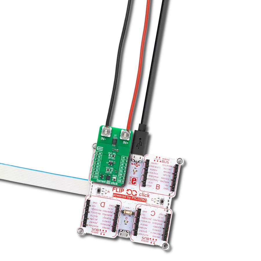
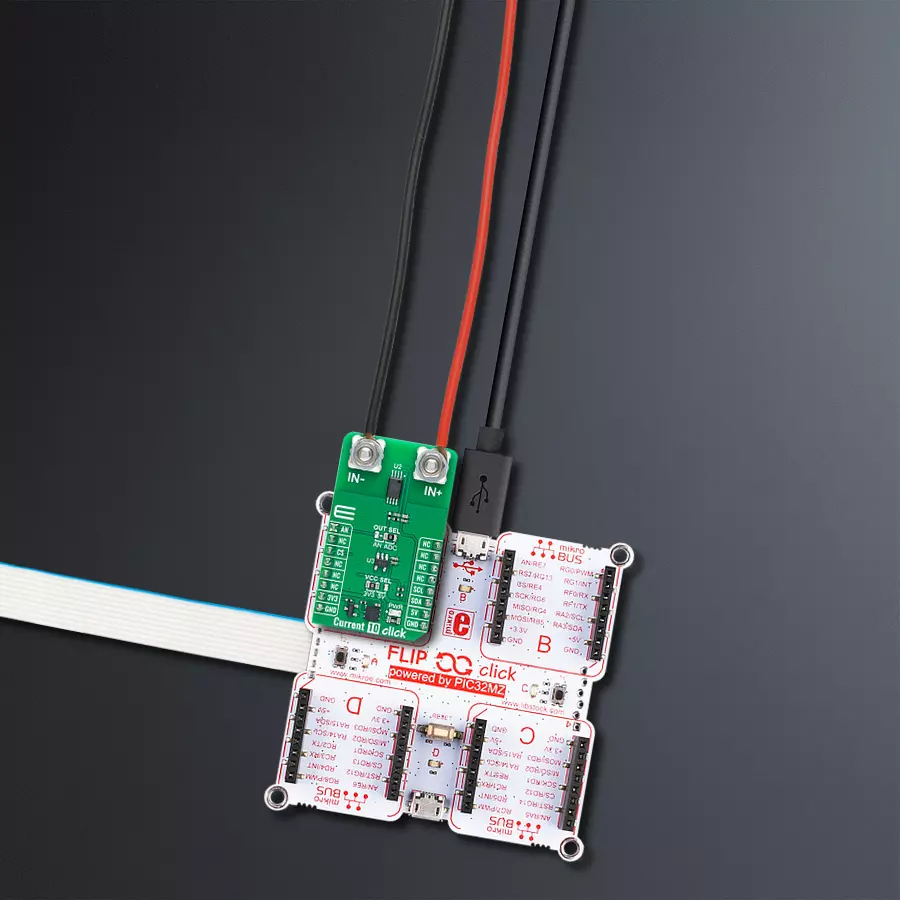
Current 10 Click is based on the CT455 (CT455-H06B5-TS08), an XtremeSense™ TMR (Tunnel Magnetoresistance) coreless current sensor from Allegro Microsystems, featuring a wide bandwidth of 1MHz. This sensor uses Allegro’s patented XtremeSense™ technology, ensuring highly accurate current measurements with extremely low noise. With its high accuracy and robust features, Current 10 Click is an excellent solution for applications requiring reliable current sensing in consumer, industrial, and enterprise applications, such as solar power inverters, battery management systems, DC/DC converters, industrial equipment, and power utility meters. The CT455 sensor
operates in a bipolar mode, detecting both positive and negative current flows, and it offers a sensitivity of 333.3mV/mT, providing precise measurement capability. Powered by a 5V supply, the CT455 can sense magnetic fields in two standard ranges of ±6mT, translated into a linear analog output voltage. This allows the board to accurately capture current changes with less than ±1.0% error over varying temperatures and supply voltages, ensuring reliable performance across various operational conditions. The CT455's output signal can be converted to a digital value using MCP3221, a successive approximation A/D converter with a 12-bit resolution from Microchip,
using a 2-wire I2C compatible interface, or sent directly to an analog pin of the mikroBUS™ socket labeled as AN. Selection can be performed via an onboard SMD jumper labeled OUT SEL, placing it in an appropriate position marked as AN and ADC. This Click board™ can operate with either 3.3V or 5V logic voltage levels selected via the VCC SEL jumper. This way, both 3.3V and 5V capable MCUs can use the communication lines properly. Also, this Click board™ comes equipped with a library containing easy-to-use functions and an example code that can be used as a reference for further development.

Features overview
Development board
Flip&Click PIC32MZ is a compact development board designed as a complete solution that brings the flexibility of add-on Click boards™ to your favorite microcontroller, making it a perfect starter kit for implementing your ideas. It comes with an onboard 32-bit PIC32MZ microcontroller, the PIC32MZ2048EFH100 from Microchip, four mikroBUS™ sockets for Click board™ connectivity, two USB connectors, LED indicators, buttons, debugger/programmer connectors, and two headers compatible with Arduino-UNO pinout. Thanks to innovative manufacturing technology,
it allows you to build gadgets with unique functionalities and features quickly. Each part of the Flip&Click PIC32MZ development kit contains the components necessary for the most efficient operation of the same board. In addition, there is the possibility of choosing the Flip&Click PIC32MZ programming method, using the chipKIT bootloader (Arduino-style development environment) or our USB HID bootloader using mikroC, mikroBasic, and mikroPascal for PIC32. This kit includes a clean and regulated power supply block through the USB Type-C (USB-C) connector. All communication
methods that mikroBUS™ itself supports are on this board, including the well-established mikroBUS™ socket, user-configurable buttons, and LED indicators. Flip&Click PIC32MZ development kit allows you to create a new application in minutes. Natively supported by Mikroe software tools, it covers many aspects of prototyping thanks to a considerable number of different Click boards™ (over a thousand boards), the number of which is growing every day.

Microcontroller Overview
MCU Card / MCU

Architecture
PIC32
MCU Memory (KB)
2048
Silicon Vendor
Microchip
Pin count
100
RAM (Bytes)
524288
Used MCU Pins
mikroBUS™ mapper
Take a closer look
Click board™ Schematic

Step by step
Project assembly

Start by selecting your development board and Click board™. Begin with the Flip&Click PIC32MZ as your development board.


Software Support
Library Description
This library contains API for Current 10 Click driver.
Key functions:
current10_calib_offset- This function calibrates the zero current offset value.current10_calib_resolution- This function calibrates the data resolution at the known load current.current10_read_current- This function reads the input current level [A].
Open Source
Code example
The complete application code and a ready-to-use project are available through the NECTO Studio Package Manager for direct installation in the NECTO Studio. The application code can also be found on the MIKROE GitHub account.
/*!
* @file main.c
* @brief Current 10 Click Example.
*
* # Description
* This example demonstrates the use of Current 10 Click board by reading and
* displaying the input current measurements.
*
* The demo application is composed of two sections :
*
* ## Application Init
* Initializes the driver and calibrates the zero current offset and data resolution
* at 3A load current.
*
* ## Application Task
* Reads the input current measurements and displays the results on the USB UART
* approximately once per second.
*
* @note
* The measurement range is approximately: +/- 75A.
*
* @author Stefan Filipovic
*
*/
#include "board.h"
#include "log.h"
#include "current10.h"
// Load current [A] used for the data resolution calibration process.
#define CURRENT10_CALIBRATING_CURRENT 3.0f
static current10_t current10; /**< Current 10 Click driver object. */
static log_t logger; /**< Logger object. */
void application_init ( void )
{
log_cfg_t log_cfg; /**< Logger config object. */
current10_cfg_t current10_cfg; /**< Click config object. */
/**
* Logger initialization.
* Default baud rate: 115200
* Default log level: LOG_LEVEL_DEBUG
* @note If USB_UART_RX and USB_UART_TX
* are defined as HAL_PIN_NC, you will
* need to define them manually for log to work.
* See @b LOG_MAP_USB_UART macro definition for detailed explanation.
*/
LOG_MAP_USB_UART( log_cfg );
log_init( &logger, &log_cfg );
log_info( &logger, " Application Init " );
// Click initialization.
current10_cfg_setup( ¤t10_cfg );
CURRENT10_MAP_MIKROBUS( current10_cfg, MIKROBUS_1 );
err_t init_flag = current10_init( ¤t10, ¤t10_cfg );
if ( ( ADC_ERROR == init_flag ) || ( I2C_MASTER_ERROR == init_flag ) )
{
log_error( &logger, " Communication init." );
for ( ; ; );
}
log_printf( &logger, " Calibrating zero current offset in 5 seconds...\r\n" );
log_printf( &logger, " Make sure no current flows through the sensor during the calibration process.\r\n" );
for ( uint8_t cnt = 5; cnt > 0; cnt-- )
{
log_printf( &logger, " %u\r\n", ( uint16_t ) cnt );
Delay_ms ( 1000 );
}
if ( CURRENT10_ERROR == current10_calib_offset ( ¤t10 ) )
{
log_error( &logger, " Calibrate offset." );
for ( ; ; );
}
log_printf( &logger, " Offset calibration DONE.\r\n\n" );
log_printf( &logger, " Calibrating data resolution in 5 seconds...\r\n" );
log_printf( &logger, " Keep the load current set at %.1fA during the calibration process.\r\n",
CURRENT10_CALIBRATING_CURRENT );
for ( uint8_t cnt = 5; cnt > 0; cnt-- )
{
log_printf( &logger, " %u\r\n", ( uint16_t ) cnt );
Delay_ms ( 1000 );
}
if ( CURRENT10_ERROR == current10_calib_resolution ( ¤t10, CURRENT10_CALIBRATING_CURRENT ) )
{
log_error( &logger, " Calibrate resolution." );
for ( ; ; );
}
log_printf( &logger, " Data resolution calibration DONE.\r\n" );
log_info( &logger, " Application Task " );
}
void application_task ( void )
{
float current = 0;
if ( CURRENT10_OK == current10_read_current ( ¤t10, ¤t ) )
{
log_printf( &logger, " Current : %.1f A\r\n\n", current );
Delay_ms ( 1000 );
}
}
int main ( void )
{
/* Do not remove this line or clock might not be set correctly. */
#ifdef PREINIT_SUPPORTED
preinit();
#endif
application_init( );
for ( ; ; )
{
application_task( );
}
return 0;
}
// ------------------------------------------------------------------------ END
Additional Support
Resources
Category:Current sensor


