Provide data for training machine learning models to recognize specific vibration patterns with FXLS8974CF and PIC32MZ2048EFM100
3-axis accelerometer for motion sensing and vibration analysis
Published Dec 02, 2024
Click board™
ML Vibro Sens Click
Dev. board
Curiosity PIC32 MZ EF
Compiler
NECTO Studio
MCU
PIC32MZ2048EFM100
Capture precise motion and vibration data for machine learning applications
A
A
Hardware Overview
How does it work?
ML Vibro Sens Click is a machine learning training tool based on the FXLS8974CF, a 3-axis low-g 12-bit digital accelerometer from NXP. Designed for applications requiring precise motion sensing, this Click board™ is an excellent choice for testing and training ML algorithms in both industrial and IoT environments. The FXLS8974CF offers the versatility of ultra-low-power operation alongside high-performance modes, ensuring efficient use in diverse scenarios. Its integrated digital features simplify data collection and reduce system power consumption, while its robust performance over extended temperature ranges enhances reliability in demanding applications, including industrial diagnostics, wearable technology, and environmental monitoring. This Click board™ incorporates two DC motors to simulate vibration stimuli for machine learning: a balanced and an unbalanced motor. The BALANCED motor generates steady "nominal" vibrations, serving as a baseline signal for training ML models in a "healthy" state. On the other hand, the UNBALANCED motor is designed to provide customizable vibration signals, ranging from low-intensity to specific frequency-based vibrations. This motor is powered via the UNB signal, which
supports PWM or PDM inputs, allowing precise modulation of vibration characteristics. Applying a continuous power signal to the unbalanced motor is not recommended due to its intensity, so a low-frequency, low-duty-cycle PWM signal is suggested for controlled vibration stimuli. The BAL signal powers the balanced motor, maintaining a stable vibration environment for baseline training. Both motors are used from the IND-YZ0412J series, known for their high-frequency vibration capabilities. The board features orange LED indicators labeled BALANCED and UNBALANCED to visually indicate motor activity, which lights up when their respective motors are active. The FXLS8974CF accelerometer is essential for ML Vibro Sens Click as it provides precise motion and vibration measurement across three axes (X, Y, Z), forming the foundation for training machine learning algorithms. It captures detailed data from the balanced and unbalanced motors, enabling the differentiation between "healthy" baseline states and anomalous conditions. With its customizable sensitivity, it supports high-performance and low-power modes, ensuring flexibility for various application needs. The FXLS8974CF communicates with the host MCU via a standard 2-
wire I2C interface, supporting clock frequencies up to 1MHz. Its I2C address can be configured through the onboard ADDR SEL jumper, offering flexibility in multi-sensor setups. Additional BT MODE jumper allows users to enable users to select between two distinct operating modes, tailoring the board's functionality. In addition to the interface pins, the board uses the INT pin, whose behavior is determined by the setting of the BT MODE jumper. In Default Mode (position 0), the INT pin acts as a programmable interrupt output, allowing the accelerometer to signal specific events - such as motion detection or threshold breaches - directly to the host MCU. Conversely, in Motion Detection Mode (position 1), the INT pin functions as a multifunction I/O, enabling the host MCU to configure motion detection thresholds or activate custom responses triggered by detected motion. This Click board™ can be operated only with a 3.3V logic voltage level. The board must perform appropriate logic voltage level conversion before using MCUs with different logic levels. Also, it comes equipped with a library containing functions and an example code that can be used as a reference for further development.

Features overview
Development board
Curiosity PIC32 MZ EF development board is a fully integrated 32-bit development platform featuring the high-performance PIC32MZ EF Series (PIC32MZ2048EFM) that has a 2MB Flash, 512KB RAM, integrated FPU, Crypto accelerator, and excellent connectivity options. It includes an integrated programmer and debugger, requiring no additional hardware. Users can expand
functionality through MIKROE mikroBUS™ Click™ adapter boards, add Ethernet connectivity with the Microchip PHY daughter board, add WiFi connectivity capability using the Microchip expansions boards, and add audio input and output capability with Microchip audio daughter boards. These boards are fully integrated into PIC32’s powerful software framework, MPLAB Harmony,
which provides a flexible and modular interface to application development a rich set of inter-operable software stacks (TCP-IP, USB), and easy-to-use features. The Curiosity PIC32 MZ EF development board offers expansion capabilities making it an excellent choice for a rapid prototyping board in Connectivity, IOT, and general-purpose applications.

Microcontroller Overview
MCU Card / MCU

Architecture
PIC32
MCU Memory (KB)
2048
Silicon Vendor
Microchip
Pin count
100
RAM (Bytes)
524288
Used MCU Pins
mikroBUS™ mapper
Take a closer look
Click board™ Schematic

Step by step
Project assembly

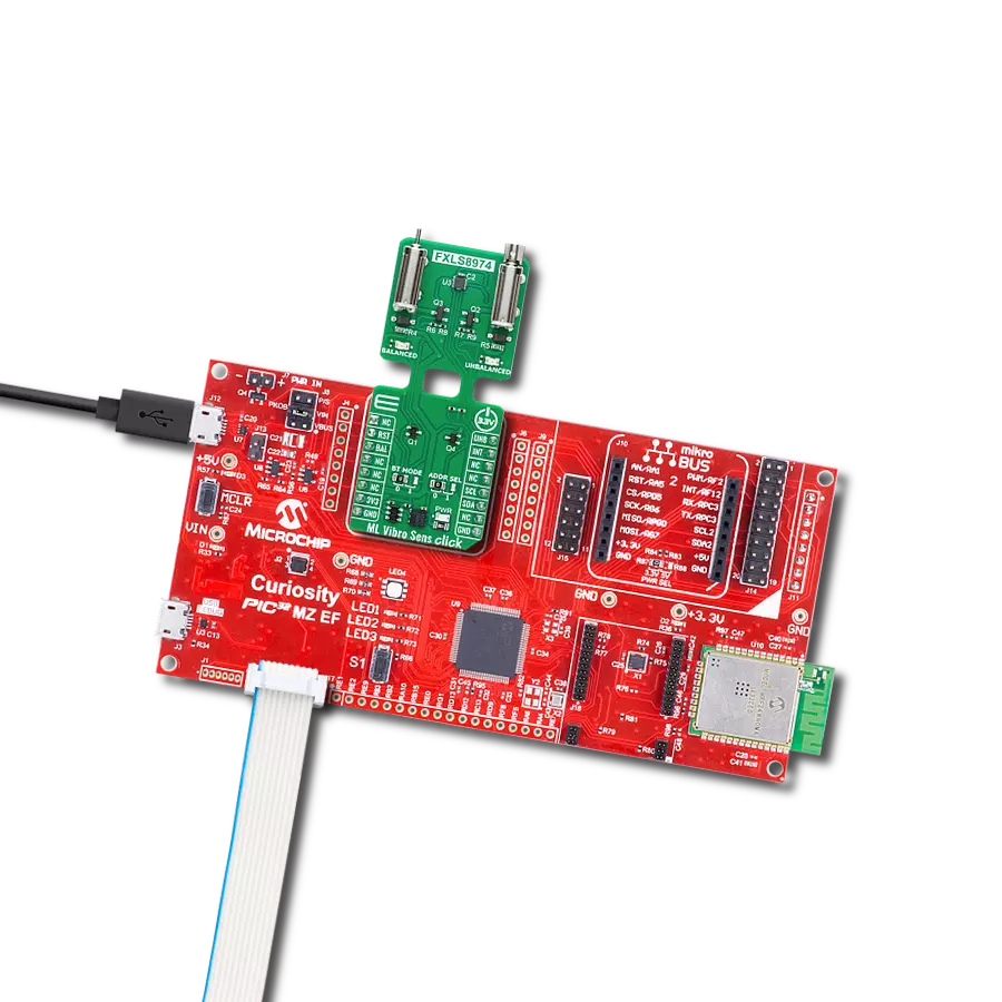
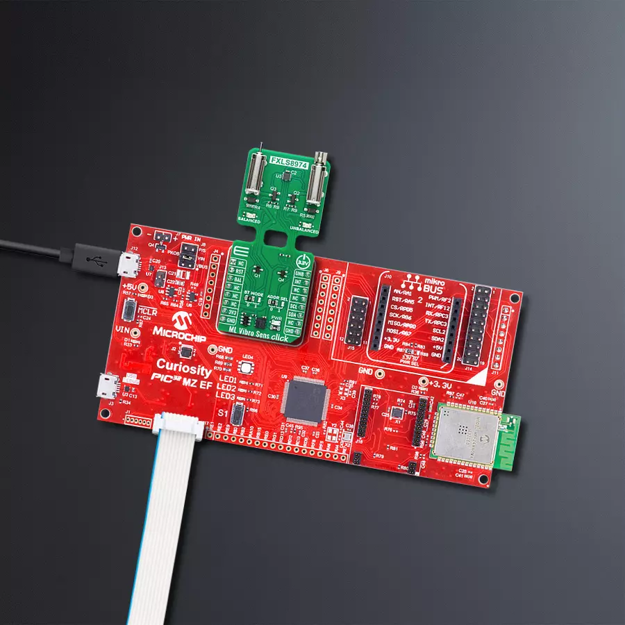
Start by selecting your development board and Click board™. Begin with the Curiosity PIC32 MZ EF as your development board.


Software Support
Library Description
This library contains API for ML Vibro Sens Click driver.
Key functions:
mlvibrosens_get_int_pin- This function returns the interrupt pin logic state.mlvibrosens_get_data- This function reads accel X, Y, and Z axis data in g and temperature in degrees Celsius.mlvibrosens_set_vibro_state- This function sets the vibro motors state.
Open Source
Code example
The complete application code and a ready-to-use project are available through the NECTO Studio Package Manager for direct installation in the NECTO Studio. The application code can also be found on the MIKROE GitHub account.
/*!
 * @file main.c
 * @brief ML Vibro Sens Click example
 *
 * # Description
 * This example demonstrates the use of the ML Vibro Sens Click board by capturing and logging
 * acceleration data on the X, Y, and Z axes, along with temperature readings. The data is output
 * over USB UART and can be visualized in real-time using tools like SerialPlot. Additionally,
 * the vibro motor state changes periodically, cycling through different vibration states for
 * added feedback.
 *
 * The demo application is composed of two sections :
 *
 * ## Application Init
 * Initializes the communication interface and configures the ML Vibro Sens Click board
 * with default settings. This setup enables an interrupt on the INT pin when data is ready,
 * sets the acceleration sensitivity to a +/-4G range, and sets the output data rate to 100 Hz.
 *
 * ## Application Task
 * Monitors the data-ready interrupt, retrieves acceleration and temperature data when available,
 * and logs it over USB UART in the format X;Y;Z;TEMP. After every 1000 data readings, the
 * vibro motor state cycles through predefined states to demonstrate the motor's functionality.
 *
 * @note
 * We recommend using the SerialPlot tool for data visualization. The temperature measurements
 * should be visualized independently. The data format for plotter is as follows: X;Y;Z;TEMP;
 *
 * @author Stefan Filipovic
 *
 */

#include "board.h"
#include "log.h"
#include "mlvibrosens.h"

static mlvibrosens_t mlvibrosens;
static log_t logger;

void application_init ( void )
{
    log_cfg_t log_cfg;  /**< Logger config object. */
    mlvibrosens_cfg_t mlvibrosens_cfg;  /**< Click config object. */

    /**
     * Logger initialization.
     * Default baud rate: 115200
     * Default log level: LOG_LEVEL_DEBUG
     * @note If USB_UART_RX and USB_UART_TX
     * are defined as HAL_PIN_NC, you will
     * need to define them manually for log to work.
     * See @b LOG_MAP_USB_UART macro definition for detailed explanation.
     */
    LOG_MAP_USB_UART( log_cfg );
    log_init( &logger, &log_cfg );
    log_info( &logger, " Application Init " );

    // Click initialization.
    mlvibrosens_cfg_setup( &mlvibrosens_cfg );
    MLVIBROSENS_MAP_MIKROBUS( mlvibrosens_cfg, MIKROBUS_1 );
    if ( I2C_MASTER_ERROR == mlvibrosens_init( &mlvibrosens, &mlvibrosens_cfg ) )
    {
        log_error( &logger, " Communication init." );
        for ( ; ; );
    }

    if ( MLVIBROSENS_ERROR == mlvibrosens_default_cfg ( &mlvibrosens ) )
    {
        log_error( &logger, " Default configuration." );
        for ( ; ; );
    }

    log_info( &logger, " Application Task " );
}

void application_task ( void )
{
    static uint8_t vibro_state = MLVIBROSENS_VIBRO_STATE_IDLE;
    static uint16_t result_num = 0;
    static mlvibrosens_data_t accel_data;

    // Wait for a data ready interrupt
    while ( mlvibrosens_get_int_pin ( &mlvibrosens ) );

    if ( MLVIBROSENS_OK == mlvibrosens_get_data ( &mlvibrosens, &accel_data ) )
    {
        log_printf ( &logger, "%f;%f;%f;%d;\r\n", accel_data.x, accel_data.y,
                                                  accel_data.z, accel_data.temperature );
    }
    if ( ++result_num > 1000 )
    {
        result_num = 0;
        if ( ++vibro_state > MLVIBROSENS_VIBRO_STATE_BOTH )
        {
            vibro_state = MLVIBROSENS_VIBRO_STATE_IDLE;
        }
        mlvibrosens_set_vibro_state ( &mlvibrosens, vibro_state );
    }
}

int main ( void )
{
    /* Do not remove this line or clock might not be set correctly. */
    #ifdef PREINIT_SUPPORTED
    preinit();
    #endif

    application_init( );

    for ( ; ; )
    {
        application_task( );
    }

    return 0;
}

// ------------------------------------------------------------------------ END
Additional Support
Resources
Category:Motion


