Achieve continuous insights into current fluctuations using ACHS-7194 and PIC18F4553
Amp Up Accuracy
Published Nov 01, 2023
Click board™
Hall Current 10 Click
Dev. board
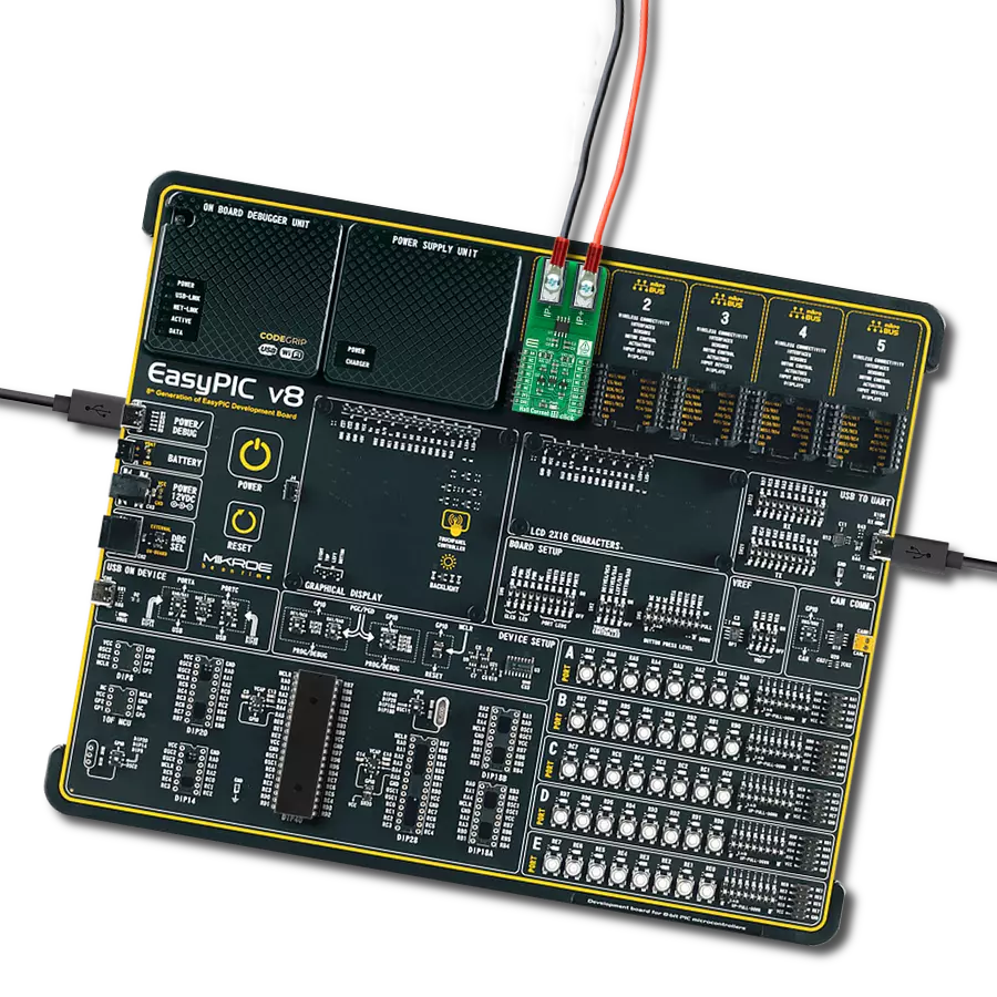
EasyPIC v8
Compiler
NECTO Studio
MCU
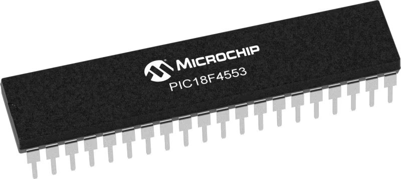
PIC18F4553
Maximize the lifespan of your equipment by utilizing our Hall-effect current sensing solution, which assists in identifying overload conditions and preventing potential damage
A
A
Hardware Overview
How does it work?
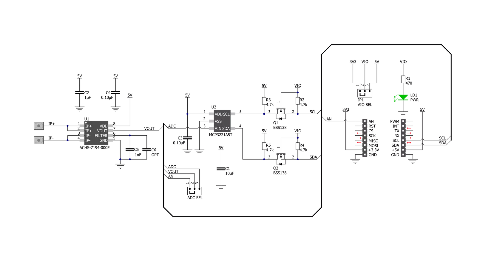
Hall Current 10 Click is based on the ACHS-7194, a Hall-effect current sensor from Broadcom Limited that sends an analog voltage proportional to the magnetic field intensity caused by the current flowing through the primary input conductor. Without a magnetic field, the output voltage is half of the supply voltage. The ACHS-7194 can detect both DC and AC, designed for the current range of ±40A. Device accuracy is optimized across the operating ambient temperature through the close proximity of the magnetic signal to the Hall sensors. The copper conductor's thickness allows the device's survival at high overcurrent conditions. The terminals of the conductive path are electrically
isolated from the signal leads. This feature enables the ACHS-7194 to be used in applications requiring electrical isolation without optoisolators or other costly isolation techniques. The ACHS-7194 also has a ratiometric output, which changes proportionally to the supply voltage. Just like that, the output voltage, analog signal, can be converted to a digital value using MCP3221, a successive approximation A/D converter with a 12-bit resolution from Microchip, using a 2-wire I2C compatible interface, or can be sent directly to an analog pin of the mikroBUS™ socket labeled as AN. Selection can be performed by onboard SMD jumper labeled ADC SEL to an appropriate position
marked as AN and I2C. With the MCP3221, data transfers at rates of up to 100kbit/s in the Standard and 400kbit/s in the Fast Mode. Also, maximum sample rates of 22.3kSPS with the MCP3221 are possible in a Continuous-Conversion Mode with a clock rate of 400kHz. This Click board™ can operate with either 3.3V or 5V logic voltage levels selected via the VIO SEL jumper. This way, both 3.3V and 5V capable MCUs can use the communication lines properly. Also, this Click board™ comes equipped with a library containing easy-to-use functions and an example code that can be used, as a reference, for further development.


Features overview
Development board
EasyPIC v8 is a development board specially designed for the needs of rapid development of embedded applications. It supports many high pin count 8-bit PIC microcontrollers from Microchip, regardless of their number of pins, and a broad set of unique functions, such as the first-ever embedded debugger/programmer. The development board is well organized and designed so that the end-user has all the necessary elements, such as switches, buttons, indicators, connectors, and others, in one place. Thanks to innovative manufacturing technology, EasyPIC v8 provides a fluid and immersive working experience, allowing access anywhere and under any
circumstances at any time. Each part of the EasyPIC v8 development board contains the components necessary for the most efficient operation of the same board. In addition to the advanced integrated CODEGRIP programmer/debugger module, which offers many valuable programming/debugging options and seamless integration with the Mikroe software environment, the board also includes a clean and regulated power supply module for the development board. It can use a wide range of external power sources, including a battery, an external 12V power supply, and a power source via the USB Type-C (USB-C) connector.
Communication options such as USB-UART, USB DEVICE, and CAN are also included, including the well-established mikroBUS™ standard, two display options (graphical and character-based LCD), and several different DIP sockets. These sockets cover a wide range of 8-bit PIC MCUs, from the smallest PIC MCU devices with only eight up to forty pins. EasyPIC v8 is an integral part of the Mikroe ecosystem for rapid development. Natively supported by Mikroe software tools, it covers many aspects of prototyping and development thanks to a considerable number of different Click boards™ (over a thousand boards), the number of which is growing every day.

Microcontroller Overview
MCU Card / MCU
Architecture
PIC
MCU Memory (KB)
32
Silicon Vendor
Microchip
Pin count
40
RAM (Bytes)
2048
Used MCU Pins
mikroBUS™ mapper
Take a closer look
Click board™ Schematic
Step by step
Project assembly

Start by selecting your development board and Click board™. Begin with the EasyPIC v8 as your development board.


Software Support
Library Description
This library contains API for Hall Current 10 Click driver.
Key functions:
hallcurrent10_read_adc- Hall Current 10 I2C ADC reading functionhallcurrent10_get_adc_volatge- Hall Current 10 get ADC voltage functionhallcurrent10_get_current- Hall Current 10 get current function
Open Source
Code example
The complete application code and a ready-to-use project are available through the NECTO Studio Package Manager for direct installation in the NECTO Studio. The application code can also be found on the MIKROE GitHub account.
/*!
* @file main.c
* @brief HallCurrent10 Click example
*
* # Description
* This library contains API for Hall Current 10 Click driver.
* The demo application reads ADC value, ADC voltage and current value.
*
* The demo application is composed of two sections :
*
* ## Application Init
* Initializes I2C driver and log UART.
* After driver initialization the app set default settings.
*
* ## Application Task
* This is an example that demonstrates the use of the Hall Current 10 Click board™.
* In this example, we read and display the ADC values and current ( mA ) data.
* Results are being sent to the Usart Terminal where you can track their changes.
*
* @author Nenad Filipovic
*
*/
#include "board.h"
#include "log.h"
#include "hallcurrent10.h"
static hallcurrent10_t hallcurrent10;
static log_t logger;
static uint16_t adc_data;
static float current;
static float adc_voltage;
void application_init ( void )
{
log_cfg_t log_cfg; /**< Logger config object. */
hallcurrent10_cfg_t hallcurrent10_cfg; /**< Click config object. */
/**
* Logger initialization.
* Default baud rate: 115200
* Default log level: LOG_LEVEL_DEBUG
* @note If USB_UART_RX and USB_UART_TX
* are defined as HAL_PIN_NC, you will
* need to define them manually for log to work.
* See @b LOG_MAP_USB_UART macro definition for detailed explanation.
*/
LOG_MAP_USB_UART( log_cfg );
log_init( &logger, &log_cfg );
log_info( &logger, " Application Init " );
// Click initialization.
hallcurrent10_cfg_setup( &hallcurrent10_cfg );
HALLCURRENT10_MAP_MIKROBUS( hallcurrent10_cfg, MIKROBUS_1 );
if ( I2C_MASTER_ERROR == hallcurrent10_init( &hallcurrent10, &hallcurrent10_cfg ) )
{
log_info( &logger, " Application Init Error. " );
log_info( &logger, " Please, run program again... " );
for ( ; ; );
}
log_info( &logger, " Application Task " );
log_printf( &logger, "--------------------------\r\n" );
Delay_ms ( 100 );
}
void application_task ( void )
{
hallcurrent10_read_adc( &hallcurrent10, &adc_data );
log_printf( &logger, " ADC Value : %d \r\n", adc_data );
Delay_ms ( 100 );
hallcurrent10_get_adc_voltage( &hallcurrent10, &adc_voltage );
log_printf( &logger, " ADC Voltage : %.2f mV \r\n", adc_voltage );
log_printf( &logger, "- - - - - - - - - - - - -\r\n" );
Delay_ms ( 100 );
hallcurrent10_get_current ( &hallcurrent10, ¤t );
log_printf( &logger, " Current : %.2f mA \r\n", current );
log_printf( &logger, "--------------------------\r\n" );
Delay_ms ( 1000 );
Delay_ms ( 1000 );
}
int main ( void )
{
/* Do not remove this line or clock might not be set correctly. */
#ifdef PREINIT_SUPPORTED
preinit();
#endif
application_init( );
for ( ; ; )
{
application_task( );
}
return 0;
}
// ------------------------------------------------------------------------ END
Additional Support
Resources
Category:Current sensor


