Accurately measure an object's tilt or orientation relative to gravity with the FXLS8971CF and PIC18LF45K80
3-axis low-g MEMS accelerometer in a Click Snap form factor
Published Jun 25, 2024
Click board™
Inclinometer 4 Click
Dev. board
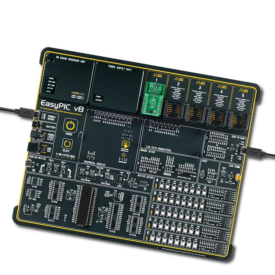
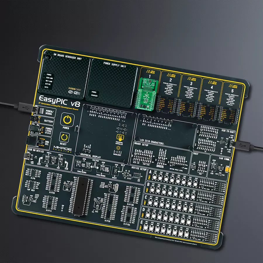
EasyPIC v8
Compiler
NECTO Studio
MCU
PIC18LF45K80
Measure the tilt or orientation of an object relative to gravity
A
A
Hardware Overview
How does it work?
Inclinometer 4 Click is based on the FXLS8971CF, a compact 3-axis low-g MEMS accelerometer from NXP Semiconductor. The FXLS8971CF offers both high-performance and low-power operating modes, with user-selectable full-scale measurement ranges of ±2/4/8/16g, providing flexibility to match different applications' specific resolution and power needs. Key features include selectable output data rates with programmable resolution and idle-time settings, a flexible sensor data-change detection function for detecting motion or no motion, and the ability to detect high-g/low-g events, freefall, and other inertial activities. It also includes a 144-byte output data buffer (FIFO/LIFO), which helps minimize system power consumption and streamline data collection for the host system. This Click board™ measures angles of slope or elevation of an object with respect to gravity's direction, suitable for a wide array of industrial and medical IoT applications, including asset tracking, equipment monitoring, smart metering, tamper detection, orientation detection, and many more. Inclinometer 4 Click is designed in a unique format supporting the newly introduced MIKROE feature
called "Click Snap." Unlike the standardized version of Click boards, this feature allows the main sensor area to become movable by breaking the PCB, opening up many new possibilities for implementation. Thanks to the Snap feature, the FXLS8971CF can operate autonomously by accessing its signals directly on the pins marked 1-8. Additionally, the Snap part includes a specified and fixed screw hole position, enabling users to secure the Snap board in their desired location. This Click board™ allows for flexible communication options, supporting both I2C and SPI interfaces. These interfaces enable communication speeds up to 1MHz for I2C and 4MHz for SPI. Users can select their preferred communication protocol by adjusting the SMD jumpers in the COMM SEL section. These jumpers, as well as the COMM 1 jumper in the Snap section, must be aligned on the same side to avoid potential issues. Aside from additional interface signals configuration, an additional SMD jumper in the Snap section labeled COMM 2 also adjusts the I2C address. Besides the interface selection jumpers, this Click board™ features an additional jumper in
the Snap section of the Click board named BOOT. This jumper allows for device boot mode selection between the default operating mode (by placing the jumper in the GND position) and enabling motion detection mode (by placing it in the VCC position). Like standard Click board™, all signals from the main sensor, in this case, the FXLS8971CF, are available on the mikroBUS™ pins. In addition to standard communication pins, the FXLS8971CF utilizes two interrupt pins, IT1 and IT2, which are particularly useful when using the Motion Detection mode. When this mode is active, the IT1 pin sets the motion detection threshold, and the IT2 pin signals that the device boot process has been completed. If this mode is inactive, both pins function as standard programmable interrupt output pins. This Click board™ can be operated only with a 3.3V logic voltage level. The board must perform appropriate logic voltage level conversion before using MCUs with different logic levels. Also, it comes equipped with a library containing functions and an example code that can be used as a reference for further development.

Features overview
Development board
EasyPIC v8 is a development board specially designed for the needs of rapid development of embedded applications. It supports many high pin count 8-bit PIC microcontrollers from Microchip, regardless of their number of pins, and a broad set of unique functions, such as the first-ever embedded debugger/programmer. The development board is well organized and designed so that the end-user has all the necessary elements, such as switches, buttons, indicators, connectors, and others, in one place. Thanks to innovative manufacturing technology, EasyPIC v8 provides a fluid and immersive working experience, allowing access anywhere and under any
circumstances at any time. Each part of the EasyPIC v8 development board contains the components necessary for the most efficient operation of the same board. In addition to the advanced integrated CODEGRIP programmer/debugger module, which offers many valuable programming/debugging options and seamless integration with the Mikroe software environment, the board also includes a clean and regulated power supply module for the development board. It can use a wide range of external power sources, including a battery, an external 12V power supply, and a power source via the USB Type-C (USB-C) connector.
Communication options such as USB-UART, USB DEVICE, and CAN are also included, including the well-established mikroBUS™ standard, two display options (graphical and character-based LCD), and several different DIP sockets. These sockets cover a wide range of 8-bit PIC MCUs, from the smallest PIC MCU devices with only eight up to forty pins. EasyPIC v8 is an integral part of the Mikroe ecosystem for rapid development. Natively supported by Mikroe software tools, it covers many aspects of prototyping and development thanks to a considerable number of different Click boards™ (over a thousand boards), the number of which is growing every day.

Microcontroller Overview
MCU Card / MCU
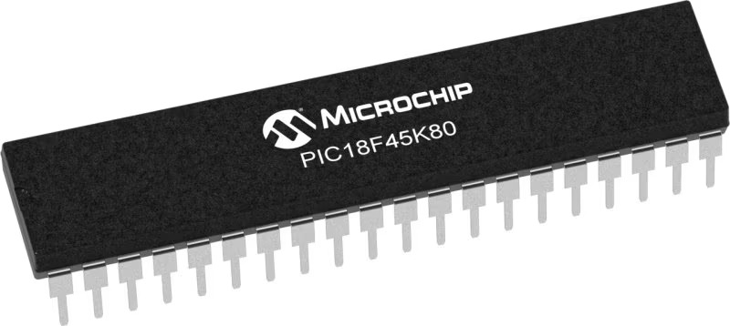
Architecture
PIC
MCU Memory (KB)
32
Silicon Vendor
Microchip
Pin count
40
RAM (Bytes)
3648
Used MCU Pins
mikroBUS™ mapper
Take a closer look
Click board™ Schematic

Step by step
Project assembly

Start by selecting your development board and Click board™. Begin with the EasyPIC v8 as your development board.


Software Support
Library Description
This library contains API for Inclinometer 4 Click driver.
Key functions:
inclinometer4_get_int2_pin- This function returns the interrupt 2 (INT2) pin logic state.inclinometer4_get_data- This function reads accel X, Y, and Z axis data in g and temperature in degrees Celsius.inclinometer4_set_mode- This function sets the device operating mode to standby or active.
Open Source
Code example
The complete application code and a ready-to-use project are available through the NECTO Studio Package Manager for direct installation in the NECTO Studio. The application code can also be found on the MIKROE GitHub account.
/*!
 * @file main.c
 * @brief Inclinometer 4 Click example
 *
 * # Description
 * This example demonstrates the use of Inclinometer 4 Click board by reading and displaying
 * accel data (X, Y, and Z axis) as well as temperature measurements on the USB UART.
 *
 * The demo application is composed of two sections :
 *
 * ## Application Init
 * Initializes the driver and performs the Click default configuration which enables data ready
 * interrupt on INT2 pin and sets full scale range to +/-2G and output data rate to 160ms.
 *
 * ## Application Task
 * Waits for a data ready interrupt, then reads and displays the accel data (X, Y, and Z axis)
 * as well as temperature measurements on the USB UART.
 *
 * @author Stefan Filipovic
 *
 */

#include "board.h"
#include "log.h"
#include "inclinometer4.h"

static inclinometer4_t inclinometer4;
static log_t logger;

void application_init ( void )
{
    log_cfg_t log_cfg;  /**< Logger config object. */
    inclinometer4_cfg_t inclinometer4_cfg;  /**< Click config object. */

    /**
     * Logger initialization.
     * Default baud rate: 115200
     * Default log level: LOG_LEVEL_DEBUG
     * @note If USB_UART_RX and USB_UART_TX
     * are defined as HAL_PIN_NC, you will
     * need to define them manually for log to work.
     * See @b LOG_MAP_USB_UART macro definition for detailed explanation.
     */
    LOG_MAP_USB_UART( log_cfg );
    log_init( &logger, &log_cfg );
    log_info( &logger, " Application Init " );

    // Click initialization.
    inclinometer4_cfg_setup( &inclinometer4_cfg );
    INCLINOMETER4_MAP_MIKROBUS( inclinometer4_cfg, MIKROBUS_1 );
    err_t init_flag = inclinometer4_init( &inclinometer4, &inclinometer4_cfg );
    if ( ( I2C_MASTER_ERROR == init_flag ) || ( SPI_MASTER_ERROR == init_flag ) )
    {
        log_error( &logger, " Communication init." );
        for ( ; ; );
    }

    if ( INCLINOMETER4_ERROR == inclinometer4_default_cfg ( &inclinometer4 ) )
    {
        log_error( &logger, " Default configuration." );
        for ( ; ; );
    }

    log_info( &logger, " Application Task " );
}

void application_task ( void )
{
    inclinometer4_data_t accel_data;

    // Wait for a data ready interrupt
    while ( inclinometer4_get_int2_pin ( &inclinometer4 ) );

    if ( INCLINOMETER4_OK == inclinometer4_get_data ( &inclinometer4, &accel_data ) )
    {
        log_printf( &logger, " X: %.3f g\r\n", accel_data.x );
        log_printf( &logger, " Y: %.3f g\r\n", accel_data.y );
        log_printf( &logger, " Z: %.3f g\r\n", accel_data.z );
        log_printf( &logger, " Temperature: %d degC\r\n\n", ( int16_t ) accel_data.temperature );
    }
}

int main ( void )
{
    /* Do not remove this line or clock might not be set correctly. */
    #ifdef PREINIT_SUPPORTED
    preinit();
    #endif

    application_init( );

    for ( ; ; )
    {
        application_task( );
    }

    return 0;
}

// ------------------------------------------------------------------------ END
Additional Support
Resources
Category:Motion


