Hear your heart's story with SFH 7060 and PIC18F45K22
Your heartbeat, your guide

Published Jul 18, 2023
Click board™
Heart Rate 9 Click
Dev. board
EasyPIC v8
Compiler
NECTO Studio
MCU
PIC18F45K22
Upgrade your solution's heart rate monitoring capabilities with our advanced sensor technology - designed to deliver accurate and consistent readings
A
A
Hardware Overview
How does it work?
Heart Rate 9 Click is based on the SFH 7060, a heart rate and pulse oximetry monitoring sensor from ams OSRAM. It utilizes a Phase Division Multiplexing technique to simultaneously measure multiple signals with zero cross-talk. This technique uses the PIC16F1779 MCU's integrated Core Independent Peripherals (CIPs) from Microchip. CIPs allow you to achieve a low-noise reflective heart rate monitor design with significantly lower BOM costs than conventional designs. This Heart Rate 9 Click board™ introduces Microchip's proprietary method (hereafter "proprietary method") of measuring multiple signals in a body using pseudorandom binary sequence generation and phase division multiplexing. This proprietary method uses a special encoding/decoding scheme to allow multiple light-emitting diodes (LED) to transmit light simultaneously with a single photodiode to condition each light from the combined lights at the receiving side. While the blood passes through the capillary blood vessels, they expand and dilate. Their light reflectance index changes accordingly. This is the basis of the photo-plethysmogram (PPM), a method used for the volumetric measurement of an organ, or in this case - blood vessels. The heart rate signal is calculated
according to the changes in the reflected green light sensed by the PD element. The Heart Rate 6 click can provide the HRM readings by placing the index finger over the optical sensor. Oxygen saturation in the blood can be determined by measuring the light absorption in the red/IR part of the spectrum. The oxygen-saturated blood absorbs more red light and less infrared than the unsaturated blood. This fact can be used to determine the oxygen saturation of the blood. The peripheral capillary oxygen saturation (SpO2) percentage ranges from 95% to 100% for a healthy adult. The challenge in a multiple signal sources system (for example, the LEDs in the case of a pulse oximeter) is that each LED must share the same photodiode. A classic solution is to turn on each light source in sequence and then take each measurement in turn. Each light source gets its slice of time in which the photodiode can get its measurement. This method is called Time-Division Multiplexing (TDM). The same principle is also applied to the TDMA-based cellular system. The drawback of the TDM approach is that adding more light sources while keeping the data processing routine the same results in more time to get a measurement from every source. Microchip's proprietary method uses a known
concept called Maximal Length (ML) sequence, a type of pseudorandom binary sequence, to generate a gold code or a reference sequence. This reference sequence is then phase-shifted using PhaseDivision Multiplexing (PDM) to drive multiple LEDs. After passing through a part of a body, the light amplitudes from these LEDs are detected by a phototransistor or photodiode and digitized with an Analog-to-Digital Converter (ADC). The digitized ADC light amplitude values are re-correlated with each LED's driving sequence. Spread spectrum techniques are known for their noise mitigation properties and ability to pass multiple signals through the same medium without interference. Thus, these measurements of each light absorption of the body can be performed substantially simultaneously with minimal interference from each other. The SFH7060, made by ams OSRAM, integrates three green, one red, one infrared emitter, and one photodiode in a reflective package. The reflective photo sensing method has become increasingly popular in developing small, wearable biometric sensors, such as those green light sensors seen in the back of smartwatches or activity tracker wristbands.


Features overview
Development board
EasyPIC v8 is a development board specially designed for the needs of rapid development of embedded applications. It supports many high pin count 8-bit PIC microcontrollers from Microchip, regardless of their number of pins, and a broad set of unique functions, such as the first-ever embedded debugger/programmer. The development board is well organized and designed so that the end-user has all the necessary elements, such as switches, buttons, indicators, connectors, and others, in one place. Thanks to innovative manufacturing technology, EasyPIC v8 provides a fluid and immersive working experience, allowing access anywhere and under any
circumstances at any time. Each part of the EasyPIC v8 development board contains the components necessary for the most efficient operation of the same board. In addition to the advanced integrated CODEGRIP programmer/debugger module, which offers many valuable programming/debugging options and seamless integration with the Mikroe software environment, the board also includes a clean and regulated power supply module for the development board. It can use a wide range of external power sources, including a battery, an external 12V power supply, and a power source via the USB Type-C (USB-C) connector.
Communication options such as USB-UART, USB DEVICE, and CAN are also included, including the well-established mikroBUS™ standard, two display options (graphical and character-based LCD), and several different DIP sockets. These sockets cover a wide range of 8-bit PIC MCUs, from the smallest PIC MCU devices with only eight up to forty pins. EasyPIC v8 is an integral part of the Mikroe ecosystem for rapid development. Natively supported by Mikroe software tools, it covers many aspects of prototyping and development thanks to a considerable number of different Click boards™ (over a thousand boards), the number of which is growing every day.

Microcontroller Overview
MCU Card / MCU
Architecture
PIC
MCU Memory (KB)
32
Silicon Vendor
Microchip
Pin count
40
RAM (Bytes)
1536
Used MCU Pins
mikroBUS™ mapper
Take a closer look
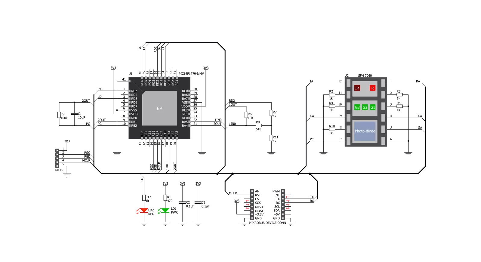
Click board™ Schematic
Step by step
Project assembly

Start by selecting your development board and Click board™. Begin with the EasyPIC v8 as your development board.


Software Support
Library Description
This library contains API for Heart Rate 9 Click driver.
Key functions:
heartrate9_generic_write- Heart Rate 9 data writing functionheartrate9_generic_read- Heart Rate 9 data reading functionheartrate9_set_rst- Sets state of the rst pin setting
Open Source
Code example
The complete application code and a ready-to-use project are available through the NECTO Studio Package Manager for direct installation in the NECTO Studio. The application code can also be found on the MIKROE GitHub account.
/*!
 * @file main.c
 * @brief Heart Rate 9 Click Example.
 *
 * # Description
 * This example reads and processes data from Heart Rate 9 Clicks.
 *
 * The demo application is composed of two sections :
 *
 * ## Application Init
 * Initializes driver and wake-up module.
 *
 * ## Application Task
 * Reads the received data and logs it.
 *
 * ## Additional Function
 * - static void heartrate9_clear_app_buf ( void ) - Function clears memory of app_buf.
 * - static err_t heartrate9_process ( void ) - The general process of collecting data the module sends.
 *
 * @note
 * Data structure is:
 *  > AA;BB;CC;DD;EE; <
 *
 *  > AA -> Data header.
 *  > BB -> Red diode.
 *  > CC -> IR diode.
 *  > DD -> Green diode.
 *  > EE -> BPM.
 *
 * @author Luka Filipovic
 *
 */

#include "board.h"
#include "log.h"
#include "heartrate9.h"

#define PROCESS_BUFFER_SIZE 200

static heartrate9_t heartrate9;
static log_t logger;

static char app_buf[ PROCESS_BUFFER_SIZE ] = { 0 };
static int32_t app_buf_len = 0;
static int32_t app_buf_cnt = 0;

/**
 * @brief Heart Rate 9 clearing application buffer.
 * @details This function clears memory of application buffer and reset it's length and counter.
 * @note None.
 */
static void heartrate9_clear_app_buf ( void );

/**
 * @brief Heart Rate 9 data reading function.
 * @details This function reads data from device and concatenates data to application buffer.
 *
 * @return @li @c  0 - Read some data.
 *         @li @c -1 - Nothing is read.
 *         @li @c -2 - Application buffer overflow.
 *
 * See #err_t definition for detailed explanation.
 * @note None.
 */
static err_t heartrate9_process ( void );

void application_init ( void )
{
    log_cfg_t log_cfg;  /**< Logger config object. */
    heartrate9_cfg_t heartrate9_cfg;  /**< Click config object. */

    /**
     * Logger initialization.
     * Default baud rate: 115200
     * Default log level: LOG_LEVEL_DEBUG
     * @note If USB_UART_RX and USB_UART_TX
     * are defined as HAL_PIN_NC, you will
     * need to define them manually for log to work.
     * See @b LOG_MAP_USB_UART macro definition for detailed explanation.
     */
    LOG_MAP_USB_UART( log_cfg );
    log_init( &logger, &log_cfg );

    // Click initialization.
    heartrate9_cfg_setup( &heartrate9_cfg );
    HEARTRATE9_MAP_MIKROBUS( heartrate9_cfg, MIKROBUS_1 );
    err_t init_flag  = heartrate9_init( &heartrate9, &heartrate9_cfg );
    if ( init_flag == UART_ERROR )
    {
        log_error( &logger, " Application Init Error. " );
        log_info( &logger, " Please, run program again... " );

        for ( ; ; );
    }

    app_buf_len = 0;
    app_buf_cnt = 0;
}

void application_task ( void )
{
   heartrate9_process();

    if ( app_buf_len > 0 )
    {
        log_printf( &logger, "%s", app_buf );
        heartrate9_clear_app_buf(  );
    }
}

int main ( void )
{
    /* Do not remove this line or clock might not be set correctly. */
    #ifdef PREINIT_SUPPORTED
    preinit();
    #endif

    application_init( );

    for ( ; ; )
    {
        application_task( );
    }

    return 0;
}

static void heartrate9_clear_app_buf ( void )
{
    memset( app_buf, 0, app_buf_len );
    app_buf_len = 0;
    app_buf_cnt = 0;
}

static err_t heartrate9_process ( void )
{
    int32_t rx_size;
    char rx_buff[ PROCESS_BUFFER_SIZE ] = { 0 };

    rx_size = heartrate9_generic_read( &heartrate9, rx_buff, PROCESS_BUFFER_SIZE );

    if ( rx_size > 0 )
    {
        int32_t buf_cnt = 0;

        if ( app_buf_len + rx_size >= PROCESS_BUFFER_SIZE )
        {
           heartrate9_clear_app_buf(  );
            return -2;
        }
        else
        {
            buf_cnt = app_buf_len;
            app_buf_len += rx_size;
        }

        for ( int32_t rx_cnt = 0; rx_cnt < rx_size; rx_cnt++ )
        {
            if ( rx_buff[ rx_cnt ] != 0 )
            {
                app_buf[ ( buf_cnt + rx_cnt ) ] = rx_buff[ rx_cnt ];
            }
            else
            {
                app_buf_len--;
            }

        }
        return 0;
    }
    return -1;
}

// ------------------------------------------------------------------------ END
Additional Support
Resources
Category:Biometrics


